
Here is some code to allow you to use a serial terminal to read and write to the PIC's registers and EEPROM.
Please sign my guestbook if you find this page useful. Please sign my guest book
; SERIAL PORT CONTROL:
;
;	PORT A0 is Serial input
;	PORT A0 is serial output
;
;	usb gmus-03 USB Serial Adapter
;
;	TX  D9 Pin 3 -[4k7]----+-----PA0
;	RX  D9 Pin 2 ----------/
;
;	GND D9 Pin 5 ---------------- 0V
Some Commands: - you can add more if you wish
; File Registers ;wAADD; write DD to register AA ; rAA; read AA and output to serial port ; ; EEPROM ; pAADD; write DD to EEPROM register AA ; gAA; read EEPROM register AA and output to serial port ; ; ; The ; executes the command. ; There needs to be a delay between each character sent to allow the PIC to process the commands. ; Do not use spaces and the command letter must be in column1 ;
The PIC buffers the characters, and uses the last buffered characters. The buffer length is checked
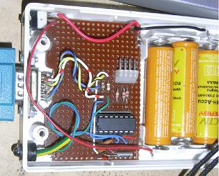
Connect the 4800 baud serial terminal using the circuit below:-
The PIC serial routines are simplex so you might as well use the same pin for TX and RX.
I have found that a PIC will output a voltage that my PC seems happy with, without the need to resort to an MAXIM rs 232 chip.
When the PIC wants to send a character to the terminal, it makes RA0 an output and sends the character. It then makes the pin an input and the main loop polls for a start bit.
You can configure the PWM module with the f; command

Run the code below into a PC 16F628 chip:
Updated 31/01/2007
:020000000628D0
:0800080009001929DF20F22094
:1000100009281A20121828200C08031909280C187E
:10002000222009280D088E0005088D000D090E05F7
:100030008F040800100891000508900011091005B0
:10004000920408000C1017086F2008000F13080016
:10005000121030280B1D08000B110C141220080080
:10006000632061200830950005080139FF3E970C98
:100070006320950B342897090C1408000F39063EAD
:100080008318073E2A3E98004528940094090510DD
:1000900083160510831205106320051463200830B1
:1000A0009500940C03080139003E050601398506C8
:1000B0006320950B512805106320831605148312C5
:1000C00008001D306528000040309600960B662819
:1000D000640008009700171E093E0F3908009700BA
:1000E000F33E031D76281A3099000800D23E031D06
:1000F0007A2888281908840017088000990F1908A1
:10010000E03E031DDE281A3099000D30452008001E
:100110001A3099001B081B1E093E0F399700970ED5
:100120001C081C1E093E0F391707A0001D081D1EC4
:10013000093E0F399700970E1E081E1E093E0F3903
:100140001707A10089301A07031DAD282008840075
:10015000210880002A304520DA2890301A07031D34
:10016000BB282008052183122108082121088000CE
:100170002A304520DA288E301A07031DCA282008A5
:100180008400000897003D304520170E3E201708D8
:100190003E20DA2899301A07031DD2282008FF20B4
:1001A0009700C3289A301A07031DDA2818212A302D
:1001B0004520DA280D3045200A304520080000305F
:1001C0008B0085018316F0308600051483121A30E7
:1001D0009900640083160230810083128C018F0124
:1001E000920108000D3045200A304520533045204B
:1001F000523045200D3045200A304520080083123A
:100200008900081408088312080083128900080076
:10021000831288008B130812081555308900AA3004
:1002200089008814081188181229081283120800FE
:0402300008000900B9
:084000000000000008000400AC
:02400E00F13F80
:044200006400320024
:00000001FF
;**************************************************************************
; SR001.ASM
;
; PROGRAM: Simple Serial Project
;
; DESCRIPTION:
;	simple serial project that receives serial commands
;   spaces are important
;
; File Regiters
;	<CR>wAADD;		write DD to register AA
;	<CR>rAA;  		read AA and output to serial port
;
; EEPROM
;	<CR>pAADD;		write DD to EEPROM register AA
;	<CR>gAA;  		read EEPROM register AA and output to serial port
;
; PRIPHERALS
;	<CR>f;			init PWM
;	; sets up PWM module
;	W92FF;	- PR2 	 - set PWM period max
;	W1532;	- CCPR1L	 - Duty Cycle / ON period
;	W8600;	- TRISB	 - All Outputs
;	W1204;	- T2CON	 - Set up Tmr 2
;	W173C;	- CCP1CON - Set up as PWM module.
;	W9265;	- PR2 	 - set PWM period for 10Khz if 4Mhz crystal.
;

;
; SERIAL PORT CONTROL:
;
;	PORT A0 is Serial input
;	PORT A0 is serial output
;
;	usb gmus-03 USB Serial Adapter
;
;	TX  D9 Pin 3 -[4k7]----+-----PA0
;	RX  D9 Pin 2 ----------/
;
;	GND D9 Pin 5 ---------------- 0V
;
; AUTHOR:  Douglas Rice
; Copyright 2004
;
;	Crystal:	4MHz
;
;	I/O used:-
;
;	; Port B is used for the LCD
;
;
;**************************************************************************

;#define pic16F84 1
#define pic16F628 1

ifdef pic16F84
	INCLUDE "p16F84.inc"

        LIST P=16F84, R=DEC
	__idlocs  0x0084
	__config  _XT_OSC&_PWRTE_ON & _WDT_OFF

	cblock 	0x0c
	endc
endif

ifdef pic16F628
	INCLUDE "p16F628.inc"
        LIST P=16F628, R=DEC
	__idlocs  0x0628
	__CONFIG _CP_OFF & _WDT_OFF & _BODEN_OFF & _PWRTE_ON & _INTRC_OSC_CLKOUT  & _MCLRE_OFF & _LVP_OFF

	cblock 0x20
	endc
endif

;--------------------------------------------------------------------------
; Sec 1. Equates and Constants
;--------------------------------------------------------------------------
; The General Purpose Registers start at the end of the
; Special Purpose Registers.

; IPMentState values
; in normal running or in time setting modes
;

; DoTimeSlice bits
; these bits are set to schedule a timer chain event
DTsS4event	EQU	0	;

RUN_BUFF	EQU	0	;

; IPtrigMenu
DTSFast			EQU	0

;--------------------------------------------------------------------------
; Sec 1.1 Button and LED
;--------------------------------------------------------------------------

BUTTON_RS232	EQU	0	; EDG  - Bottom Buttom
BUTTON_DOWN	EQU	6	; EDG  - Bottom Buttom

;--------------------------------------------------------------------------
; Sec 2.0 Variables
;--------------------------------------------------------------------------
; Variables start 0x0C
;

;	DoTimeSlice Bits, to schedule, set bit

	cblock
DoTimeSlice

IPnew
IPlast
IPbuttonEvent

IPnewFast
IPlastFast
IPbuttonEventUp

IPtrigMenu

; variables used by Serial input and output routines
RStxTemp
RSloopCnt
RSdelayCnt
RSin
RSout

; Serial input buffer
RSipBuffCnt ; input buffer counter
; start of buffer
RScmd
RSAa		;
RSaA		;
RSDd		;
RSdD		;
RSterminator
; end of buffer

; temporary variables
RSaddr
RSdata
;
ENDC


; *********** I/O EQUATES **************
PORTA           EQU  5          ; 5 BITS
PA0             EQU  0		; Serial Out
PA1             EQU  1		; Serial In

PORTB           EQU  6
RS232tx         EQU  PA0	; Serial Out
RS232rx         EQU  PA0	; Serial In needs to be equal to BUTTON_RS232

;--------------------------------------------------------------------------
; Sec 3. MACROS
;--------------------------------------------------------------------------


TEST_STRADDLE	MACRO	START
	if high( $ ) != high( START )
	    Error "Table straddles Page Boundary " + Start
	endif
	endm

;--------------------------------------------------------------------------
; Sec 4. Program Code
;--------------------------------------------------------------------------
	ORG     0
	GOTO    Start

	ORG 	4
	RETFIE
	GOTO 	Intrtn

;--------------------------------------------------------------------------
; Sec 4.1	Main Program Init Code
;--------------------------------------------------------------------------

Start
	CALL 	INinit
	CALL	INsayHello
	GOTO	MainLoop


;--------------------------------------------------------------------------
; Sec 4.2	Main Program
;--------------------------------------------------------------------------

MainLoop
		CALL	IPtimesliceFast

		; test for rising edge
		BTFSC	IPbuttonEventUp,BUTTON_RS232	; RS232 input start
		CALL	IPrs232

		MOVF	DoTimeSlice,w
		Bz		MainLoop

		BTFSC	DoTimeSlice,RUN_BUFF
		CALL	DLrunBuff

		GOTO 	MainLoop


;--------------------------------------------------------------------------
; Sec 5.	Subroutines, procedures and functions
;--------------------------------------------------------------------------


;--------------------------------------------------------------------------
; Sec 5.1	Button Poll Routine
;--------------------------------------------------------------------------

IPtimeslice
		;	--_____	button press
		;	----___

		;	__-----  /IPnew
		;	----___  IPlast
		;	__--___
		;
		;
		;
		; This reads all Port A inputs and looks for Press
		MOVFW	IPnew
		MOVWF	IPlast
		MOVFW	PORTA
		MOVWF	IPnew
		; IP last contains new setting, IPlast contains previous
		; look for falling edges
		COMF	IPnew,W
		ANDWF	IPlast,W
		; now force IPbuttonEvent bits to high for new pressed button
		; the service routine should reset the bit to clear the event.
		IORWF	IPbuttonEvent,F
		RETURN

IPtimesliceFast
		; Look for rising edges
		MOVFW	IPnewFast
		MOVWF	IPlastFast
		MOVFW	PORTA
		MOVWF	IPnewFast

		COMF	IPlastFast,W
		ANDWF	IPnewFast,W
		IORWF	IPbuttonEventUp,F
		RETURN
;--------------------------------------------------------------------------
; Sec 5.2
;--------------------------------------------------------------------------

;--------------------------------------------------------------------------
; Sec 5.2	.1 run process on request
;--------------------------------------------------------------------------

DLrunBuff
	BCF	DoTimeSlice,RUN_BUFF

	MOVFW	RSin
	CALL	RSbuffInput
	return


;--------------------------------------------------------------------------
; Sec 5.3	 Button Input functions
;--------------------------------------------------------------------------


IPdownPressed
	BCF IPbuttonEvent,BUTTON_DOWN
	return


IPrs232
	BCF IPbuttonEventUp,BUTTON_RS232
	GOTO RSrs232in


;--------------------------------------------------------------------------
; Sec 5.4	 Clock Chain Routine
;--------------------------------------------------------------------------

CLtimeslice
		;
		BTFSS	INTCON,T0IF
		RETURN

		; TMR0 timeout
		BCF		INTCON,T0IF
		BSF		DoTimeSlice,DTsS4event

		CALL	IPtimeslice
		RETURN


;--------------------------------------------------------------------------
; Sec 5.5 	Serial Input Routine
;--------------------------------------------------------------------------

;**************************************************
RSrs232in

; Test is in main loop or uncomment code below to
; spin for a start bit
;		CLRWDT
;		BTFSS	PORTA,RS232rx
;		GOTO	RSrs232in


		CALL	RSdelayBit			; delay through Stop Bit
		CALL 	RSdelayHalfBit		; delay halfway into first bit

		movlw	8
		movwf	RSloopCnt
RSrs232inL0
		MOVFW	PORTA
		ANDLW	 1<< RS232rx		; mask off bit
		ADDLW	-1<< RS232rx		; use ripple carry to move into C
		RRF		RSin,F

		CALL	RSdelayBit
		DECFSZ	RSloopCnt,f
		goto	RSrs232inL0

		; test for Stop bit
		COMF	RSin,f
		BSF		DoTimeSlice,RUN_BUFF
		RETURN


;--------------------------------------------------------------------------
; Sec 5.6 	Serial Output Routines
;--------------------------------------------------------------------------


RSwrtHexNibble	; currently only displays 0..9, A..F
	ANDLW	0x0F
	ADDLW	0x06	; is it A..F, if so trigger a digit overflow
	SKPNDC
	ADDLW	7; subtract 10, then add 'A'-'0'
	ADDLW	0x30-6	; Subtract extra 6 added to cause DC
	MOVWF	RSout
	GOTO	RStxChar

RStxChar
	;
	; Output Start Bit
	; Start bit is low, data bits are inverted
	;

	movwf	RStxTemp
	comf	RStxTemp,f
	BCF		PORTA,RS232tx
	MOVLW	~( 1 << RS232tx )

	; Make RS232 pin an ouput while transmitting character
	BSF		STATUS, RP0
	MOVWF	TRISA
	BCF		STATUS, RP0


	; 4800 baud output
	; move the char into RStxtemp, it is destroyed.

	; ADDED 31/01/2007
	; zzz_-xxxxxxxx__

	;
	; Do one more stop bit for luck
        ;
	; This was needed on my XP machine
	; but has not been needed before.
	;

	;
	BCF		PORT_RS232,RS232tx
	call	RSdelayBit
	; END of code ADDED 31/01/2007
	;

	; move the char into RStxtemp, it is destroyed.
	;Start Bit
	BSF		PORTA,RS232tx

	call	RSdelayBit
	movlw	8
	movwf	RSloopCnt

RStxCharLp1

	; After start bit, which is 1, then test each bit
	; I need to set PA:0 to same as LSB RStxTemp
	; this compares PA:0 with RStxTemp so see if it needs toggling
	; The xorwf PORTA,f causes the bit to be toggled if required.

	RRF		RStxTemp,f
	movfw	STATUS
	andlw	1 << C			; mask off bit
	addlw   ( 1 << RS232tx) -1	; shift bit by using a ripple carry
	xorwf	PORTA,W			; Doeas output need toggling ?
	andlw	1 << RS232tx		; Mask off output pin
	xorwf	PORTA,f			; Toggle output pin if needed
	call	RSdelayBit			; delay bit


	decfsz	RSloopCnt
	goto	RStxCharLp1

	; apply stop bit
	BCF		PORTA,RS232tx
	call	RSdelayBit
	call	RSdelayBit

	; Make RS232 pin an input so that main loop can test for start bit
	BSF		STATUS, RP0
	BSF		TRISA,  RS232tx
	BCF		STATUS, RP0

	RETURN


; timing functions to delay serial routines for a bit or half bit.

RSdelayHalfBit
		MOVLW	0x1D		; shorten delay as edge detector takes about 22 us for 4800 baud
		GOTO	RSdelayBit0

RSdelayBit
		NOP
		MOVLW	0x40	 ; for 4800 baud

RSdelayBit0
		MOVWF	RSdelayCnt
RSdelayBit1	DECFSZ	RSdelayCnt		; 1
		GOTO	RSdelayBit1		; 2 clk
		CLRWDT
		RETURN


;--------------------------------------------------------------------------
; Sec 5.7 	Serial Output Format Routines
;--------------------------------------------------------------------------

RSasciiToNibble
	MOVWF	RSin
	; if 0..1 then 0x30 to 0x39
	; if A..F then 0x41 to 0x46
	; if a..f then 0x61 to 0x66
	; test if bit 4 set and assume a letter or number
	BTFSS	RSin,4
	ADDLW	0x09		; letter so add 9
	ANDLW	0x0F		; mask of nibble
	return


;--------------------------------------------------------------------------
; Sec 5.8 	Serial Input Buffer Routine
;--------------------------------------------------------------------------

; take serial input CAADD and put into buffer
; if char id ; the do command
; if char is CR reset buffer pointer
; if buff end then reset buff pointer


RSipbuffStart	EQU RScmd
RSipbuffEnd	EQU RSterminator

RSbuffInput
	MOVWF	RSin
	; look for line feed and reset buff cnt
	ADDLW	-0x0D
	BNZ		RSbuffInput1
	MOVLW	RSipbuffStart
	MOVWF	RSipBuffCnt
	RETURN

RSbuffInput1
	; end of line command - do command
	ADDLW	-';'+0x0D
	BNZ		RSbuffInput2
	GOTO	RSbuffInputProcess

RSbuffInput2
	; Store the current time into the next register.
	MOVFW	RSipBuffCnt
	MOVWF	FSR
	MOVFW	RSin
	MOVWF	INDF
	INCFSZ	RSipBuffCnt,f
	MOVFW	RSipBuffCnt

	ADDLW	-(RSipbuffEnd+1)
	; Check if the end of memory
	SKPZ
	GOTO	RSbuffInputEnd1
	MOVLW	RSipbuffStart
	MOVWF	RSipBuffCnt

	; reset cursor
	MOVLW	0x0D
	CALL 	RStxChar
	RETURN


RSbuffInputProcess
	MOVLW	RSipbuffStart
	MOVWF	RSipBuffCnt

	MOVFW	RSAa
	; if 0..1 then 0x30 to 0x39
	; if A..F then 0x41 to 0x46
	; if a..f then 0x61 to 0x66
	; test if bit 4 set and assume a letter or number

	BTFSS	RSAa,4
	ADDLW	0x09		; letter so add 9
	ANDLW	0x0F		; mask of nibble
	MOVWF	RSin
	SWAPF	RSin,F

	MOVFW	RSaA
	BTFSS	RSaA,4
	ADDLW	0x09		; letter so add 9
	ANDLW	0x0F		; mask of nibble
	ADDWF	RSin,w
	MOVWF	RSaddr

	MOVFW	RSDd
	BTFSS	RSDd,4
	ADDLW	0x09		; letter so add 9
	ANDLW	0x0F		; mask of nibble
	MOVWF	RSin
	SWAPF	RSin,F

	MOVFW	RSdD
	BTFSS	RSdD,4
	ADDLW	0x09		; letter so add 9
	ANDLW	0x0F		; mask of nibble
	ADDWF	RSin,w
	MOVWF	RSdata

	; CALL 	RStxChar

	; got to end of buffer so process. does not allow for backspace

	; Write to file register
	MOVLW	-'w'
	ADDWF	RScmd,w	; test to see if command is s, if so save into register.
	bnz  	RSbuffInput3

	MOVFW	RSaddr
	MOVWF	FSR

	MOVFW	RSdata
	MOVWF	INDF


	MOVLW	'*'
	CALL 	RStxChar
	GOTO	RSbuffInputEnd


RSbuffInput3

	; put octet in EEPROM
	MOVLW	-'p'

	ADDWF	RScmd,w	; test to see if command is s, if so save into register.
	bnz  	RSbuffInput4

	MOVFW	RSaddr
	CALL	EEsetAddr

	BANKSEL	RSdata
	MOVFW	RSdata
	CALL	EEwrt

	MOVFW	RSdata
	MOVWF	INDF

	MOVLW	'*'
	CALL 	RStxChar

	GOTO	RSbuffInputEnd


RSbuffInput4
	; read from file register
	MOVLW	-'r'
	ADDWF	RScmd,w	; test to see if command is s, if so save into register.
	bnz  	RSbuffInput5

	MOVFW	RSaddr
	MOVWF	FSR

	MOVFW	INDF
	MOVWF	RSin

RSbuffInput4display
	MOVLW	'='
	CALL 	RStxChar

	SWAPF	RSin,w
	CALL	RSwrtHexNibble

	MOVFW	RSin
	CALL	RSwrtHexNibble

	GOTO	RSbuffInputEnd


RSbuffInput5
	; get from EEPROM register
	MOVLW	-'g'
	ADDWF	RScmd,w	; test to see if command is s, if so save into register.
	bnz  	RSbuffInput6

	MOVFW	RSaddr
	CALL	EEread
	MOVWF	RSin

	GOTO	RSbuffInput4display


RSbuffInput6
	; Initilize PWM
	MOVLW	-'f'
	ADDWF	RScmd,w	; test to see if command is s, if so save into register.
	bnz  	RSbuffInput7
	CALL	PWinit;
	MOVLW	'*'
	CALL 	RStxChar
	GOTO	RSbuffInputEnd

RSbuffInput7

RSbuffInputEnd

	MOVLW	0x0D
	CALL 	RStxChar

	MOVLW	0x0A
	CALL 	RStxChar

RSbuffInputEnd1

    return

;--------------------------------------------------------------------------
; Sec 5.9 Initilization code -
;--------------------------------------------------------------------------


INinit
	; Enable Interupts
	MOVLW	H'00'
	MOVWF	INTCON

	CLRF PORTA ;Initialize PORTA by setting
	;output data latches
	BANKSEL CMCON
	MOVLW 0X07 ;Turn comparators off and
	MOVWF CMCON ;enable pins for I/O


	banksel	TRISB
	MOVLW	0XF0
	MOVWF	TRISB
	MOVLW	~( 1 << RS232tx )	; Make PORTA 3:0 INPUTS.
	MOVWF	TRISA
	banksel	0

	; reset input buffer
	MOVLW	RSipbuffStart
	MOVWF	RSipBuffCnt

	; Change Prescaler
	CLRWDT

	; Configure Tmr 0
	BSF		STATUS,RP0
	; Set up prescaller for 8192 / 16 = 512 ticks perseconds.

	MOVLW	0x0 + 2 	; For Tmr0 0=/2, 1=/4, 2=/8,3=/16
	MOVWF	OPTION_REG
	BCF		STATUS,RP0

	; Configure Tmr 1
	MOVLW	0x0 | 1<<TMR1ON | 3 <<T1CKPS0
	MOVWF	T1CON


	CLRF	DoTimeSlice
	CLRF	IPbuttonEvent
	CLRF	IPbuttonEventUp


INsayHello
	; print out power on message
	MOVLW	0x0D
	CALL 	RStxChar

	MOVLW	0x0A
	CALL 	RStxChar

	MOVLW	'S'
	CALL 	RStxChar

	MOVLW	'R'
	CALL 	RStxChar

	MOVLW	0x0D
	CALL 	RStxChar

	MOVLW	0x0A
	CALL 	RStxChar
	return


;--------------------------------------------------------------------------
; Sec 5.10 	EEprom Routines for 16F628
;--------------------------------------------------------------------------

EEread
		; w contains address
		banksel	EEADR
		MOVWF	EEADR
		BSF		EECON1,RD
		MOVFW	EEDATA
		banksel	0
		RETURN

EEsetAddr
		banksel	EEADR
		MOVWF	EEADR
		RETURN

EEwrt		; blocking, EEADR and EEDATA set up.
		;		BSF	STATUS,RP0
		banksel 	EEDATA
		MOVWF	EEDATA
		BCF		INTCON,GIE
		BCF		EECON1,EEIF
		BSF		EECON1,WREN
		MOVLW	0x55
		MOVWF	EECON2
		MOVLW	0xAA
		MOVWF	EECON2
		BSF		EECON1,WR
		; Now wait for EEwrt to finish write
EEwaitForWrt	; block until EEPROM write has finished.
		BCF		EECON1,WREN	; disable EROM

		;
		;NOTE: On some chips, this loop prevents the EEPROM write from working.
		;      Comment out this loop.
		;
		BTFSC	EECON1,WR
		GOTO	EEwaitForWrt
		BCF		EECON1,EEIF	; EEPROM finished
		; BCF	STATUS,RP0

		banksel	0
		RETURN

;--------------------------------------------------------------------------
; Sec 5.11	Routines to set up PWM on 16F628
;--------------------------------------------------------------------------


PWinit	; set up the PWM

	; Move the PWM period into PR2

	MOVLW	0
	CALL	EEread

	BANKSEL	PR2
	MOVWF	PR2

	MOVLW	0
	MOVWF	TRISB

	MOVLW	1
	CALL	EEread

	BANKSEL	CCPR1L
	MOVWF	CCPR1L


	MOVLW	1 << TMR2ON
	MOVWF	T2CON

	BANKSEL	CCP1CON
	MOVLW	1<< CCP1X | 1<< CCP1Y | ( .12 << CCP1M0	)
	MOVWF	CCP1CON

	RETURN


;--------------------------------------------------------------------------
; Sec 6.0		Interrupt Routines
;--------------------------------------------------------------------------

Intrtn
		; Which Interupt ?
		; No Context Save in these routines.
;		BTFSC	INTCON,2
;		GOTO	IntTmr0
;		BTFSC	INTCON,1
;		GOTO	Intfint
;		BTFSC	INTCON,0
;		GOTO	IntRbport
IntTmr0
;		BCF INTCON,2
		RETFIE
Intfint
;		BCF INTCON,1
;		RETFIE
IntRbport
;		BCF INTCON,0
		RETFIE

;--------------------------------------------------------------------------
; Program End
;--------------------------------------------------------------------------

LastProgWord

;--------------------------------------------------------------------------
; Sec 7.0		EEPROM data
;--------------------------------------------------------------------------
		ORG	0x2100
		; first 2 on and off are general ones
		DE	.100,.50  ; 4

	cblock
LastVar
	endc
               END
This is one of my mosted visited pages!