| INTRO | SPEC | PHOTOS
| CIRCUIT | NOTES | PINOUTS
| GRAPHS 20/01/06 |
BLOG
| MEASUREMENT BLOG | CALCULATOR AND BLOG FORM
| Another CALCULATOR
| Blog converted to CSV output for plotting
| Blog converted and plotted with SVG - use firefox
| SC001_multiChip.asm
| SC001_multiChip.lst
|
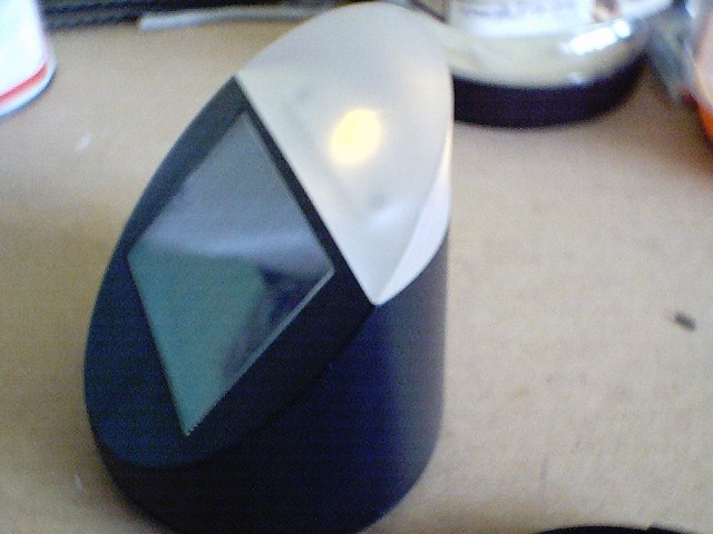
I purchased two of those solar powered lights.
They worked quite well in the summer, but in the autumn, they never seemed to be on for very long. I was quite disappointed.
How long is the LED on for? Is the battery big enough, or is the solar panel too small?
I wanted to measure how long the battery was being charged for and the how long the LED is on for.
Could I use a PIC with A/D and a serial EEPROM to measure how long the LED was on , how long the battery was being charged, and see if the design was optimised.
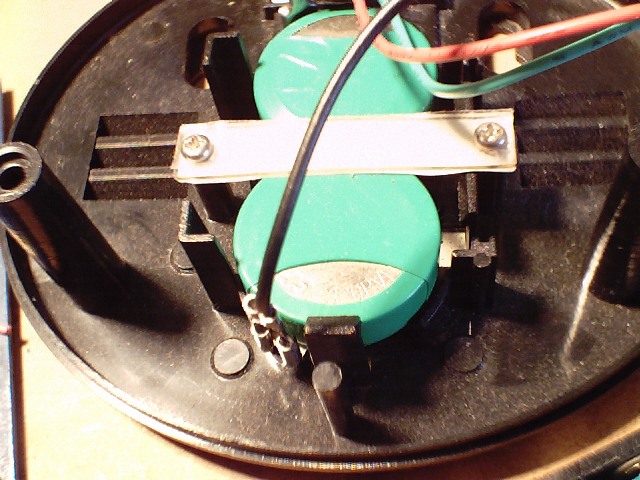
I traced the circuit of the solar light, and using a couple of cheap alarm clocks as timers I could measure the Charging duration and the on time.
The alarm clocks are the Quartz mechanical types, I used a transistor to turn on the battery, and therefore I could measure the on time for up to 12 hours.
Reset the time to 12:00 when you leave, come back within 12 hours and see what the time is now and you have a cheap timer!
You have to use a mechanical clock, not an LCD one, as the the LCD ones reset when you remove the power. You can buy dummy AA batteries from Maplin, which makes connecting to the clock much easier.
To measure the charge time with an alarm clock, I replaced the series diode from the Solar cell to the battery with a transistor Base Emitter.
I then used the transistor to turn on the battery to the clock.
Even in February, I was getting 9 hours of charge, Using another clock, I could measure how long the LED was on for. I connected the Clock across the LED, as when it is on, The clock is on. However, this did not work very well as the clock takes power in pulses every second, and the solar garden light circuits uses a Schmitt trigger to keep the light on.
The next thing was to use a PIC with some A/D converters and a serial EEPROM, and log the voltages around the circuit.
The serial EEPROM was too difficult to achieve, so I used a counter approach.
I had an array of counters, which were incremented depending upon what was happening. Every tick, the values were output in hex as serial and could be logged using hyper-terminal, captured and processed.
The counters were:
; count, time, solar cell, bright, dim ,
MmcntTime – Incremented on every tick
MmcntSolarCell – incremented if the solar cell was charging
MmcntBright – incremented if the Solar Garden Light LED was bright
MmcntDim – incremented if the Solar Garden Light LED was bright
MmcntVbatt – incremented if the Solar Garden Light's battery is above a value.
You could leave it for the day, and come in when it was dark, save the counts, and the time you read them and reset the counts for the next day.
The cycle for the day is:
1)It is dark and the Garden light's Battery is exhusted.
Reset the counters, as nothing really is happening
2)Dawn and the battery starts to charge.
3) Dusk and the solar cell voltage falls below the battery voltage, and stops charging the battery
4) Dusk and the LED comes on bright
5) Dark and the battery is almost exhusted that the LED goes dim.
In the winter I could reset the counters before I went to bed, in the summer, the LED was still on, and dawn was too early to get up for.
Measure the Solar cell to work out how it is working.
Log the values to a serial EEPROM so that the data can be plotted.
Run this for a year
Currently I have a simple logger SR003_multichip.
This uses a single 16F676. It uses the simple serial code from http://www.dougrice.plus.com/hp/LCD1300/index.html
It also uses TMR1 to tick the chip.
My first logger simply measured the voltages around the Solar Garden light, and incremented counters depending if the voltages suggested that the battery was being charged, the LED was on, was bright or was dim.
These were continually reported to an rs232 terminal.
When reseting the chip, write down the time, leave it for about 24 hours and record the counts and actual time.
I wrote a simple web page to process the counts. You entered the start and stop times and it calculated the times and voltages.
Illustration 1: PIC 16F676 pins
�
Illustration 2: EEprom
�
Requirements
; v6 = Vsolar,
; V5 = Vbattery
; V4 = VtopOfLED
|
Function |
Pin |
Comment |
|
Vsolar |
9,RC1/AN5 |
Used to measure the solar cell volatage, Clammped to Diode and Vbattery. |
|
Vbattery |
12, RA1,AN1,VREF |
Set this to Vref to get max range of AtoD when measuring the voltage across the LED resistor. Used to measure Battery voltage |
|
VtopOfLED |
10, RC0/AN4 |
Used to measure LED current, so brightness. |
|
Feedback LED |
8, RC2/AN6 |
Used to Indicate a status. |
|
Serial TX/RX |
13, RA0/AN0/CIN+/ICSPDAT as SR003multichip uses this. |
Use 4K7 resistor for half duplex serial . Possible use on change interupt. |
|
EEPROM SCL |
5, RC5 |
I2C clock |
|
EEPROM SDA |
6, RC4 |
I2C data |
|
Log Tick from external Clock |
4, RA3 |
On ve edge store the Counts into the EEPROM and zero the Counts. Input only |
|
32kHz Crystal |
2, RA5/T1CKI/OSC1/CLKIN |
Not used yet |
|
32kHz Crystal |
3, RA4/T1G/AN3/OSC2/ |
0 |
|
Battery |
1, |
VDD VDD Power — Positive supply |
|
GND |
14 |
VSS VSS Power — Ground reference |
|
ICSPDAT TTL CMOS Serial Programming Data I/O |
13,RA0/AN0/CIN+/ICSPDAT |
RA0/AN0/CIN+/ICSPDAT RA0 TTL CMOS Bi-directional I/O w/ programmable pull-up and Interrupt-on-change AN0 AN — A/D Channel 0 input CIN+ AN Comparator input ICSPDAT TTL CMOS Serial Programming Data I/O |
|
ICSPCLK ST — Serial Programming Clock |
12,RA1/AN1/CIN-/VREF/ICSPCLK |
RA1/AN1/CIN-/VREF/ ICSPCLK RA1 TTL CMOS Bi-directional I/O w/ programmable pull-up and Interrupt-on-change AN1 AN — A/D Channel 1 input CIN- AN — Comparator input VREF AN — External Voltage reference ICSPCLK ST — Serial Programming Clock |
Illustration 3: Essential circuit of the Solar Garden Light
�
Webcam pictures
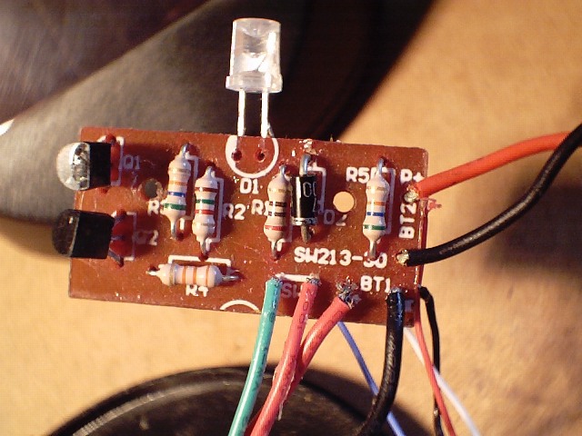
The Circuit for the logger is:
This circuit was used for the experiment in 2006
On 29/09/2008, it was found that the performance of the AtoD is much worse if the RS232 is connected to PA0. The voltage on PA0 is -0.65 volts and this makes the AtoD convert very sensitive to series resistence on the AN4,AN5,AN6 inputs.
NOTE: ONLY WHEN RS232 IS CONNECTED TO PA0, AND PA0 is -0.65 V

The resistor in series with the AtoD converter affects the measured ADRES value.

different resistors are inserted between Vdd and the AtoD pin Vref++ is set to Vdd.
Vdd ---+--------------------->Vdd
       +--[resistor]--------->AtoD

resistor	ADRES	dADRES/dkR	dR/dADRES
0		1006
1000		992	-14		-71.43
2000		976	-16		-62.5
3000		964	-12		-83.33
4700		941	-13.53		-73.91
5600		929	-13.33		-75
7500		907	-11.58		-86.36
8200		895	-17.14		-58.33
9100		885	-11.11		-90
If the RS232 circuit is moved to RC5, which is not an ANx pin, the AtoD convert works much better. When measuring the Value goes to 0x3FF when he pin is connected to Vref via a 10k resisitor.
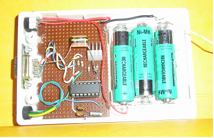
Made up on vero board
�
�
The Logger runs off an un regulated battery. The solar cell charges two NiCa cells, so the voltages are clamped to the NiCa cell voltages.
To provide a more stable voltage, a blue LED is used as a voltage reference as well as an indication of sampling.
The LED is turned on during the measurements, and provides a reference of about 3.25 volts. Pick an LED with a high forward voltage. It needs to be higher than the volatages to be measured.
The serial ouput was captured throughout the day and some of the samples plotted
The PIC's output was captured with a terminal program, pasted into a web page text area. The web page converted the HEX to decimal and converted the values to voltages. This output was pasted into microsoft works 4.5, and the graphs pasted into IFANView and saved as GIFs.
The battery never got enough charge. At twilight, the battery was discharged by the 1K5 resistor R6 in the diagram above. The LED never came on!
In the middle of the day, the solar panel was angled at about 45 degrees to the Sun, which was adjusted late afternoon.
The next graph is the year's counts plotted. Remember, that the logger increments the count every 15 seconds if the measured voltage matches the condition.
Quite frankly its a bit of a dissapointment. The on time of the light was very poor. I was surprised how long the SolarCell is charging. However, the currrent is very small.
EQUATION 7-1: ACQUISITION TIME
TACQ = Amplifier Settling Time + Hold Capacitor Charging Time + Temperature Coefficient
     = TAMP + TC + TCOFF
     = 2us + TC + [(Temperature -25C)(0.05u/C)]
Tc   = CHOLD (RIC + RSS + RS) ln(1/2047)
     = -120pF (1k. + 7k. + 10k.) ln(0.0004885)    // ln( 1/2047 ) = -7.62413058566128952912456837248005
     = 16.47us
Tacq = 2us + 16.47us + [(50C -25C)(0.05u/C)
     = 19.72us

Note
1: The reference voltage (VREF) has no effect on the equation, since it cancels itself out.
2: The charge holding capacitor (CHOLD) is not discharged after each conversion.
3: The maximum recommended impedance for analog sources is 10 k.. This is required to meet the pin
leakage specification.
re-calculate TC and Tacq Paste values from PIC SR003MultiChip.asm