Many scans of www.eio.com's discussion groups finally turned up trumps after three years.
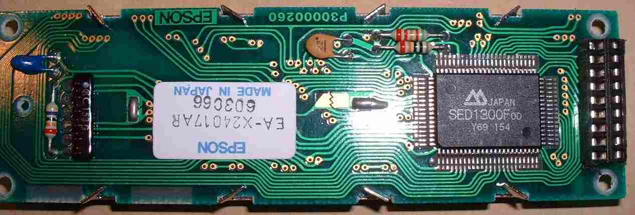
The controller is controlled by a standard Z80 style 8 bit bus, and needs a 1Mhz clock, so it is not a very useful display to use with a a PIC16F84, needing some 10 control lines.
Any information in this web page is indicative only. You are expected to establish if it is accurate.
I have only spent a few evenings soldering up the demo board, modifying my PIC16F628 Serial Monitor Program, and writting this web page.
My old web page with other LCD information
It needs to clocked at about 1Mhz, which is connected to ENB.
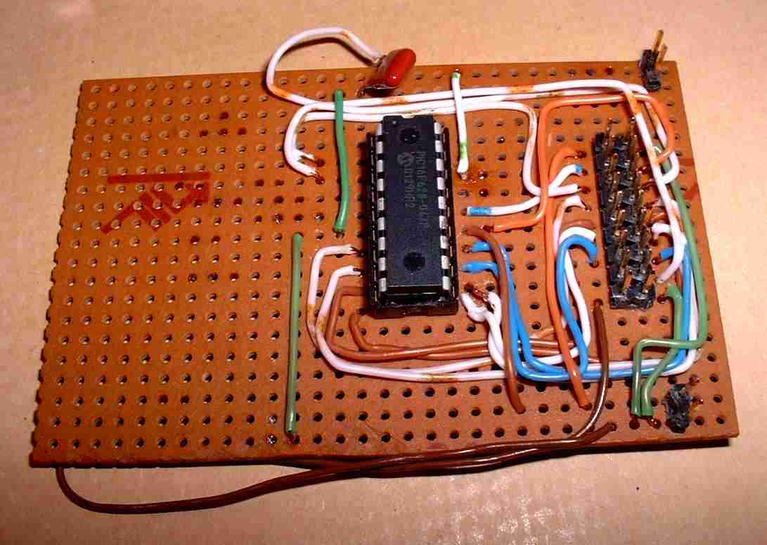
Here is the circuit of my demo breadboard:
The connections from the PIC16F628 are:
PortA:

A0	- See PIC16F628 Serial Monitor Program
A1	N/C
A2	LCD module /WR Pin 11
A3	LCD module A0  Pin 10


PortB:

B0 - B7 connect to D0 to D7


LCD Module:
-	LCD module A0  Pin 10 connect to 47nF capacitor	connected to ground. Module has 500K pull up resitor.
ENB	PIC16F628 Clock Out.

PIN	Function / comment
1	Vdd
2	D0
3	D1
4	D2
5	D3
6	D4
7	D5
8	D6
9	D7
10	A0	Address 0
11	/WR
12	/RD
13	ENB	connect 500kHz to 2MHz clock -
14	/CS	connect to GND
15	/RESET	connect a 47nF capacitor to ground.
16	/Vout 	connect via 20K VR to GND to adjust contrast
17	Vss
18	not connected
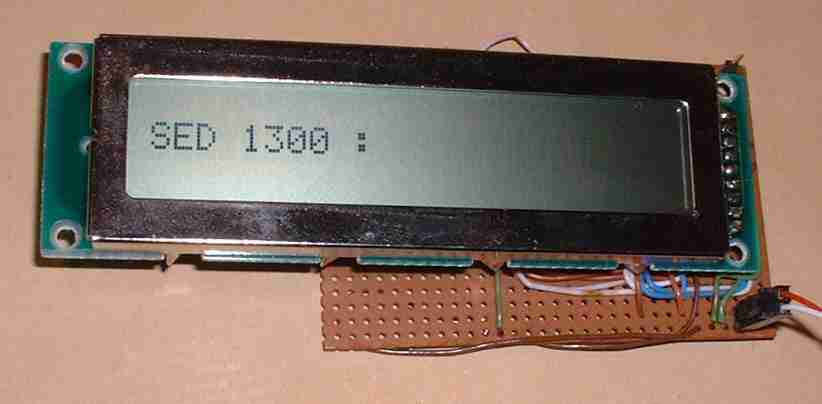
;--------------------------------------------------------------------------
; Sec 5.12	Routines to Control the Epson SED1300 LCD controller
;--------------------------------------------------------------------------

LCwrtData
	MOVWF	LCbuff

	BANKSEL  TRISA
	MOVLW	0x1
	MOVWF	TRISA
	CLRF	TRISB
	BANKSEL  PORTA

	MOVLW	0x0C
	MOVWF	PORTA
	GOTO	LCwrt

LCwrtCmd
	MOVWF	LCbuff

	BANKSEL  TRISA
	MOVLW	0x1
	MOVWF	TRISA
	CLRF	TRISB
	BANKSEL  PORTA

	MOVLW	0x04
	MOVWF	PORTA

LCwrt


	MOVFW	LCbuff
	MOVWF	PORTB

	GOTO 	$+1

	BCF		PORTA,2
	GOTO	$+1
	GOTO	$+1
	BSF		PORTA,2
	CALL	LCdelay

	RETURN

LCdelay
	MOVLW	0xFF
LCdelayBit0
	MOVWF	LCdelayCnt
LCdelayBit1
	GOTO 	$+1
	DECFSZ	LCdelayCnt		; 1
	GOTO	LCdelayBit1		; 2 clk
	CLRWDT
	RETURN


LCinit
	MOVLW	SED1300systemReset
	CALL	LCwrtCmd
	CALL	LCdelay
	CALL	LCdelay

	MOVLW	SED1300systemReset
	CALL	LCwrtCmd
	CALL	LCdelay
	CALL	LCdelay

	MOVLW	SED1300displayOn
	CALL	LCwrtCmd


	MOVLW	SED1300clearDisplayData
	CALL	LCwrtCmd
	CALL	LCdelay
	CALL	LCdelay


	MOVLW	SED1300displayOn
	CALL	LCwrtCmd

	MOVLW	'S'
	CALL	LCwrtData

	MOVLW	'E'
	CALL	LCwrtData

	MOVLW	'D'
	CALL	LCwrtData

	MOVLW	' '
	CALL	LCwrtData
	MOVLW	'1'
	CALL	LCwrtData
	MOVLW	'3'
	CALL	LCwrtData
	MOVLW	'0'
	CALL	LCwrtData
	MOVLW	'0'
	CALL	LCwrtData
	MOVLW	' '
	CALL	LCwrtData
	MOVLW	':'
	CALL	LCwrtData

	RETURN
Here is the code used in my Serial Monitor Program. See PIC16F628 Serial Monitor Program
I modified my serial Monitor program PIC 16F628 Code SR002.ASM and added extra commands;
Code serial Monitor program PIC 16F628 Code SR002_SED1300.ASM for SED1300 display.
; Serial Commands:-
;
; There are two modes:- Command mode and literal mode.
;
; On power up, after displaying SED 1300 : the display is in literal mode, displays charters straight to display.
;
; A <ESC> toggles between Literal and Command mode
;
; In literal mode the characters sent are put on the display.
; A <CR> clears the display and resets the cursor.
;
; The only Control character interpreted is <CR>.
;
; In Command Mode the following commands are recognised.
;
; (Do not use spaces, <BS> and <DEL> or cursor keys)
;
; SED1300 LCD controller commands
;	<CR>dDD;		write DD to SED1300 controller as data
;	<CR>cDD; 		write DD to SED1300 controller as command
;	<CR>i;		init chip and display SED1300 :
;	<ESC>         Toggles back to literal mode
;
; File Regiters
;	<CR>wAADD;		write DD to register AA
;	<CR>rAA;  		read AA and output to serial port
;
;
; EEPROM
;	<CR>pAADD;		write DD to EEPROM register AA
;	<CR>gAA;  		read EEPROM register AA and output to serial port
;
; PRIPHERALS
;	<CR>f;			init PWM
;	; sets up PWM module
;	W92FF;	- PR2 	 - set PWM period max
;	W1532;	- CCPR1L	 - Duty Cycle / ON period
;	W8600;	- TRISB	 - All Outputs
;	W1204;	- T2CON	 - Set up Tmr 2
;	W173C;	- CCP1CON - Set up as PWM module.
;	W9265;	- PR2 	 - set PWM period for 10Khz if 4Mhz crystal.
;
;
; SERIAL PORT CONTROL:
;
;	PORT A0 is Serial input
;	PORT A0 is serial output
;
;	usb gmus-03 USB Serial Adapter
;
;	TX  D9 Pin 3 -[4k7]----+-----PA0
;	RX  D9 Pin 2 ----------/
;
;	GND D9 Pin 5 ---------------- 0V
Build this code with Microchip's MPLAB.
;--------------------------------------------------------------------------
; Sec 5.12	Epson SED1300 command constants
;--------------------------------------------------------------------------
SED1300systemReset			EQU	0x10
SED1300clearDisplayData	EQU	0x01
SED1300cursorAtHome		EQU	0x02
SED1300cursorReturn		EQU	0x03
SED1300setCursoDirectionInc	EQU	0x04
SED1300setCursoDirectionDec	EQU	0x05
SED1300cursorInc		EQU	0x06 ; one char, does not affect ram
SED1300cursorDec		EQU	0x07
SED1300setCursorFont_		EQU	0x08
SED1300setCursorFont5x7		EQU	0x09
SED1300_cursorBlinkOff		EQU	0x0A
SED1300_cursorBlinkOn		EQU	0x0B
SED1300cursorOff		EQU	0x0E

SED1300cursorOn 		EQU	0x0F
SED1300displayOff		EQU	0x0C
SED1300displayOn		EQU	0x0D
SED1300displaySuppressOff	EQU	0x20
SED1300displaySuppressOn	EQU	0x60 ; only works while cursor is on
SED1300setCursorAddress		EQU	0x80 ; + position 0..0x17