This is based on a Wireless World article by N Darwood in November 1982.
It listed a way of generating 3, 5, and 7 phase sinewaves.
It suggested itteraing the equations:
  A=A+n*(B-C)
  B=B+n*(C-A)
  C=C+n*(A-B)
Using the starting conditions
  A=0
  B=0.866
  C=-B
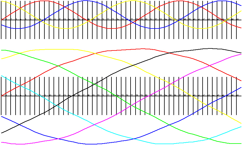
This does produce a three phase signal. Why?
So what really are the bracketed terms?
In the starting conditions, A=0, B = sin 2pi/3, C = sin 4 pi /3
The step size is choosen as SquareRoot? 3 * n
Here is a plot using the awk script below.
Some AWK that generates curves:
  ####################################################
  #
  #	T3phase.awk - A simple demo of three phase sinewave
  #
  ####################################################
BEGIN {
	FS	= ","
	lastX 	= 0
	lastY 	= 0
	re 	= 4
	im 	= 0
	lastRe	= re
	lastIm	= im
	n	= 1 / 4
	# Start the DXF file
	F_header()
        A=0
	B=0.866
	C=-B
for ( x = 0 ; x < (3.14*2*1/n-1) ; x ++ ) {
		line( x,-14,x+1,-14,0)
		line( x,4-14,x,-4-14,0)
		text( x, 0-14, 0,  " "+x)
}
#n = 1 / 8
        A=0
	B=0.866
        B=4
	C=-B
		lastA = A
		lastB = B
		lastC = C
for ( x = 0 ; x < (3.14*2*1/n-1) ; x ++ ) {
		A=A+n*(B-C)
		B=B+n*(C-A)
		C=C+n*(A-B)
		line( x,lastA-14,x+1,A-14,1)
		line( x,lastB-14,x+1,B-14,2)
		line( x,lastC-14,x+1,C-14,5)
		lastA = A
		lastB = B
		lastC = C
	}
  }
  END {
  # draw Axis
  #	line( 0,0,100,0,0)  # black
  #	line( 0,1,100,1,1)  # red
  #	line( 0,2,100,2,2)  # yellow
  #	line( 0,3,100,3,3)  # green
  #	line( 0,4,100,4,4)  # cyan
  #	line( 0,5,100,5,5)  # blue
  #	line( 0,6,100,6,6)  # magenta
  #	line( 0,7,100,7,7)  # Black
  #	line( 0,8,100,8,8)  # black
  #	line( 0,9,100,9,9)  # black
	# And finally tidy up the DXF file
	F_end()
}
I did a select all of the DXF opened by DeltaCAD? and pasted this into Serif Draw 7.0, and did a view in browser, which I saved.
 ####################################################
 #
 #	T3phase.awk - A simple demo of three phase sinewave
 #
 #  bmawk -f t3ph.awk -f dxf_fns.awk t.txt > t3ph.dxf
 #
 #
 ####################################################
BEGIN {
	FS	= ","
	lastX 	= 0
	lastY 	= 0
	re 	= 4
	im 	= 0
	lastRe	= re
	lastIm	= im
	n	= 1 / 8
	# Start the DXF file
	F_header()
        A=0
	B=0.866
	C=-B
YD = 14
for ( x = 0 ; x < (3.14*2*1/n-1) ; x ++ ) {
		line( x,-YD,x+1,-YD,0)
		line( x,4-YD,x,-4-YD,0)
		text( x, 0-YD, 0,  " "+x)
}
        A=0
	B=0.866
        B=4
	C=-B
	C=-1
	lastA = A
	lastB = B
	lastC = C
for ( x = 0 ; x < (3.14*2*1/n-1) ; x ++ ) {
		A=A+n*(B-C)
		B=B+n*(C-A)
		C=C+n*(A-B)
		line( x,lastA-YD,x+1,A-YD,1)
		line( x,lastB-YD,x+1,B-YD,2)
		line( x,lastC-YD,x+1,C-YD,5)
		lastA = A
		lastB = B
		lastC = C
}
# 7 phase
        A=0
	B=4
	C=0
        C=0
YD=30
for ( x = 0 ; x < (3.14*2*1/n-1) ; x ++ ) {
		line( x,-YD,x+1,-YD,0)
		line( x,4-YD,x,-4-YD,0)
		text( x, 0-YD, 0,  " "+x)
}
        A=0
	B=4
        B=4
	C=-B
	A=0*10.0
	B=0.78*10.0
	C=0.97*10.0
	D=0.43*10.0
 #	E=-0.43*10.0
 #	F=-0.97*10.0
 #	G=-0.78*10.0
	E=-D
	F=-C
	G=-B
		lastA = A
		lastB = B
		lastC = C
		lastD = D
		lastE = E
		lastF = F
		lastG = G
for ( x = 0 ; x < (3.14*2*1/n-1) ; x ++ ) {
		A=A+n*(B-C+D-E+F-G)
		B=B+n*(C-D+E-F+G-A)
		C=C+n*(D-E+F-G+A-B)
		D=D+n*(E-F+G-A+B-C)
		E=E+n*(F-G+A-B+C-D)
		F=F+n*(G-A+B-C+D-E)
		G=G+n*(A-B+C-D+E-F)
		line( x,lastA-YD,x+1,A-YD,1)
		line( x,lastB-YD,x+1,B-YD,2)
		line( x,lastC-YD,x+1,C-YD,3)
		line( x,lastD-YD,x+1,D-YD,4)
		line( x,lastE-YD,x+1,E-YD,5)
		line( x,lastF-YD,x+1,F-YD,6)
		line( x,lastG-YD,x+1,G-YD,7)
		lastA = A
		lastB = B
		lastC = C
		lastD = D
		lastE = E
		lastF = F
		lastG = G
	}
 }
 END {
 # draw Axis
 #	line( 0,0,100,0,0)  # black
 #	line( 0,1,100,1,1)  # red
 #	line( 0,2,100,2,2)  # yellow
 #	line( 0,3,100,3,3)  # green
 #	line( 0,4,100,4,4)  # cyan
 #	line( 0,5,100,5,5)  # blue
 #	line( 0,6,100,6,6)  # magenta
 #	line( 0,7,100,7,7)  # Black
 #	line( 0,8,100,8,8)  # black
 #	line( 0,9,100,9,9)  # black
	# And finally tidy up the DXF file
	F_end()

 }