Modeling Telephony Hybrids using 2 x 2 Matrices
Copyright Douglas Rice, doug.h.rice@btinternet.com , 2005,2008,2023
Previous version published on 06/20/2008 20:04:34 | Further Notes...| britishtelephones.com has these:- Teaching material explaining how GPO 700 phones work | GPO 746 circuit diagram
Summary:- these matrices model 2 wire hybrids used in telephones and can be multiplied together. The end to end gains or losses can be calculated.
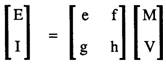
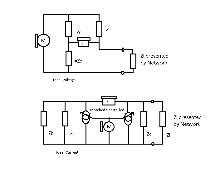
The 2x2 matrix are based on these circuits that model a two wire telephone.
Optionally, append a termination, then use convert() a few times to get the required ratio.
Example end to end and Animate Z presented to Phone.
Norton ( V := IZ ) and Tevenin ( I := V/Z ) and the Telephone.
It is thought that a circuit can be represented as a voltage source in series with an impedance Z and is thought to be equivalent to a current source in parallel with impedance Z.
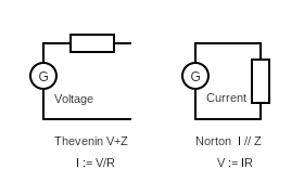
Ohms law: V := I*R; or V := I*Z;
Superposition theory.
You can use superposition theory, if the circuit is linear.
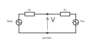
The Near Voltage is not affected by the Far voltage. So V depends on IZ. Let V:=IZ; In a real circuit, this is constrained by the power supplies.
Kirchoff's current and voltage theory
The sum of the current flowing into a node is zero. The sum of the voltages around a loop is zero
A phone and line
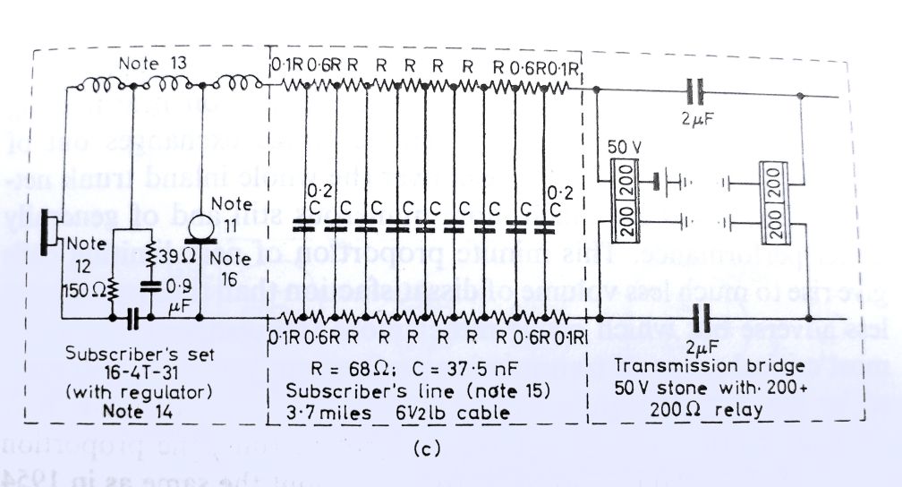
Below is a reference telephone circuit from DL Richard's book "Telecommunications by Speech" from 1970's
A Phone line is two wires of equal length and equal impedance. The voltage across the phone is midway between the power supply voltage. The circuits for the 2x2 matrices are drawn unbalanced.
A Hybrid circuit using a "wheatstone" bridge.
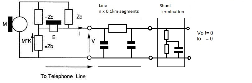
It is important to understand the following salient points about these ideal components. The microphone is a ideal voltage source, and so it has zero impedance. This is the Tevenin equivalent circuit. The earpiece is the Norton equivalent circuit. It has infinite impedance, hence it draws no current through =Zc and =Zb causing no voltage drop across =Zb, hence for signals coming down the line the voltage across the earpiece is equal to the line voltage.
Use Shunt Termination when you need Io =0 and Vo != 0
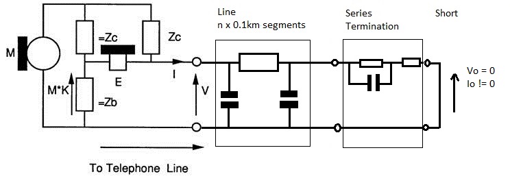
Use Series Termination when you need Vo =0 and Io != 0
1 Putting a network together
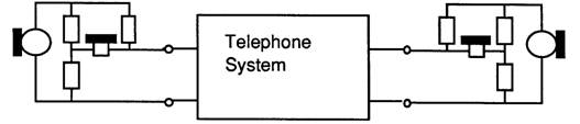
Two telephones and some line make a telephone connection, ignoring the exchange. The circuit below shows the complete network:
Multiplying the matrices together results in:

The use of OLR and STMR allude to the Loudness Ratings. These should be OLR' and STMR'. This is an allusion, as OLR and STMR are calculated at 14 frequencies as defined in ITU P.79 and also in the PABX requirments document.
Other Hybrid exampled..
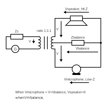
Consider this circuit. The Voltage sources are Lo-Z so the voltage across them is 0 if driven by the other voltage.
Also, for the transformer with turns ratio 1:1:1, if you apply voltage to one winding, the voltage on the other windings are the same.
So the current flowing in the secondary depends on the Z connected across the winding.
Considering this, if Zc == Zbalance, we can see this in the Telephone Hybrids below.
A Telephone Hybrid circuit, used for broadcast.
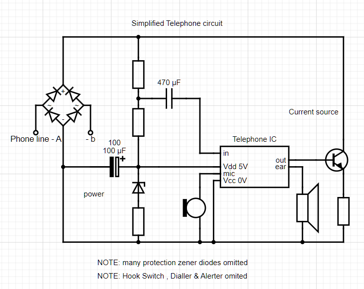
Simplified GPO 746 phone circuit
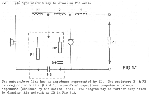
britishtelephones.com has these:- Teaching material explaining how GPO 700 phones work | GPO 746 circuit diagram
2 ABCD Parameter basics
ABCD parameters are a method of characterising a two-port network in terms of the input and output voltages and currents. They are used as the matrices that contain them can be chained together like the bits in a telephone network that they model.
On this web page all voltages, currents, pressures and sensitivities are in linear, complex number (a+jb) representation unless dB is explicitly mentioned.
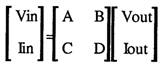
Below is a definition of the two port network and the ABCD parameters.
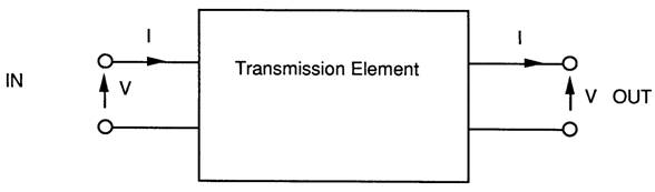
ABCD Matrix representation.
The concept of working out the inputs based on the outputs contradicted my knowledge of audio Amplifiers, where the output was based on the input!
input o->- A1 ->- A2->- A3 ->- A4 ->-o output
It allows the matrices to be chained together. We want to know "output/input" ratios or the gain.
input := [A1][A2][A3][A4]outputs
{
A Series impeadance uses:
  Vin  :=  [ 1 Z ] Vout
  Iin      [ 0 1 ] Iout

A Shunt impeadance uses:
  Vin  :=  [ 1  0 ] Vout
  Iin      [1/Z 1 ] Iout
}
Once a program has been written to chain these together the impedance looking into the network can be calculated as shown below:
Zin=Vin/lin and Vout = ZIoad * lout.
so:
For each frequency work out [r]:=[r]*[n] using:-
PROCEDURE multmat(nar,nai,nbr,nbi,ncr,nci,ndr,ndi:REAL);
{multiplies the complex two by two matries [r]:=[r]*[n]}
BEGIN
  ar:=rar;ai:=rai;
  br:=rbr;bi:=rbi;
  cr:=rcr;ci:=rci;
  dr:=rdr;di:=rdi;

  rar:=ar*nar-ai*nai+br*ncr-bi*nci;
  rai:=ar*nai+ai*nar+br*nci+bi*ncr;

  rbr:=ar*nbr-ai*nbi+br*ndr-bi*ndi;
  rbi:=ar*nbi+ai*nbr+br*ndi+bi*ndr;

  rcr:=cr*nar-ci*nai+dr*ncr-di*nci;
  rci:=cr*nai+ci*nar+dr*nci+di*ncr;

  rdr:=cr*nbr-ci*nbi+dr*ndr-di*ndi;
  rdi:=cr*nbi+ci*nbr+dr*ndi+di*ndr;
END;  {multmat}
3 The 2*2 Matrix model of a telephone
If a model for a telephone can be written down as a 2 by 2 matrix then the same program can be used to multiply the matrices together and calculate the telephone performance.
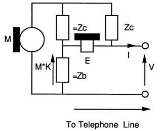
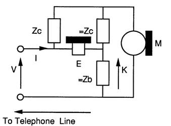
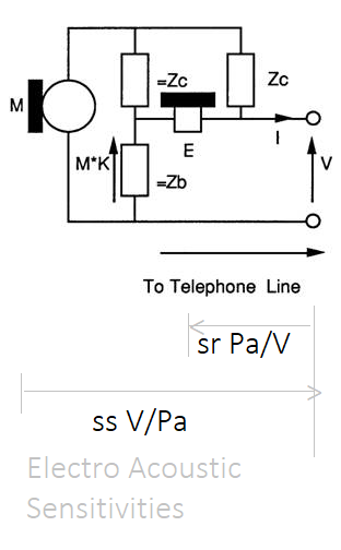
As far as the transmission is concerned the 2 wire telephone is in essence is a Wheatstone bridge. The line is the unknown impedance, the microphone is the generator and the earpiece is the detector. The diagram below shows the circuit:

It is important to understand the following salient points about the components.
The microphone is a ideal voltage source, and so it has zero impedance.
The earpiece has infinite impedance, hence it draws no current through =Zc and =Zb causing no voltage drop across =Zb, hence for signals coming down the line the voltage across the earpiece is equal to the line voltage.
Zc and Zb are complex impedances which vary with frequency.
As the microphone has zero impedance Zc is the impedance presented to the line.
Zb is an impedance, which, if connected across the line terminals to replace the line would result in zero sidetone. =Zb ( pronounced equalZb) and =Zc are impedances which equal Zb and Zc respectively.
If Zb replaces the line, =Zc and =Zb ensure that the voltages due to microphone at each end of the earpiece are exactly equal, resulting in zero volts across the earpiece.
For signals from the microphone the voltage across the earpiece is the line voltage minus the voltage across =Zb. The voltage across =Zb is only due to the microphone voltage. There can be no voltage across the microphone due to signals coming down the line as the microphone shorts out any voltage across =Zc and =Zb by virtue of its zero impedance.
=Zb and =Zc form a potential divider to divide the Microphone voltage which is used to reduce sidetone.
K is an attenuation constant.
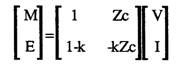
From the circuit a set of equations can be formulated and expressed in matrix form:


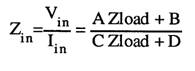
From this diagram the following equations are derived:
M=l*Zc+V
K= (=Zb/(=ZB+=Zc))
E=V-K*M using the equation for M we get:
E=V-K*(l*Zc+V)
E=V(1-K)-K*Zc*l
In Matrix form we get for the near end telephone:
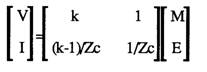
If the Telephone is at the far end of the line rearrangement gives:


V=E+KM
Zc I = M-V using the equation for V we get:
Zc I = M-(E+KM)
Zc I = (1-K)M -E
I = (1-K)*M/Zc -E/ZC
The sign of I is reversed, so:-
I = (K-1)*M/Zc +E/ZC
Note: The line current is reversed for ABCD matrix compatibility!
Normally the sending sensitivity Ss is the matched sensitivity so M is twice the line voltage in the models shown above. Different hybrid matrices were used with this factor allowed for.
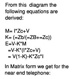
[ in ] = [ A B ] [ out ]
C D
This allows components and hybrids to be appended, component by component,
as the output become the inputs of the appended box.
[ in ] = [ ] [ ] [ ] [ ] [ out ]
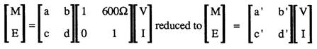
{ ABCD 2x2 matrix, work out the inputs based on the outputs,
which explains my procedure names. }
PROCEDURE twoto4(zcr,zci,zbr,zbi:REAL);
{This models the hybrid inputing 4 wire to 2 wire
[ M ] = [ ] [V]
[ E ] [ ] [I] }
PROCEDURE fourto2(zcr,zci,zbr,zbi:REAL);
{This models the hybrid inputing 2 wire to 4 wire
[ V ] = [ ] [ M ]
[ I ] [ ] [ E ] }
= } - { = } - { =
Append a phone, line , exchange, line, phone
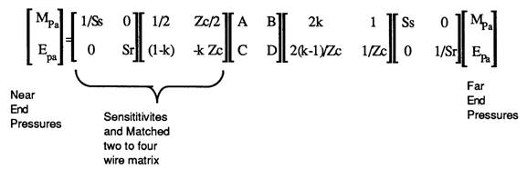
4 The 2*2 matrix model for Hybrids as found in PABX 2 wire line cards.
For a hybrid, M is replaced by Vin, and E is replaced by a differential amplifier producing Vout, matching impedances on the four wire side are ignored or accommodated in the four wire gains, They do not exist in a digital exchange, as in a digital exchange the voltages are encoded and sent digitally inside the exchange.
There is a model for a four wire exchange with two wire interfaces. This model is simplified by splitting the model into to the three matrices listed below:
a) 2 to 4 wire Hybrid,
b) 4 wire gain/ loss matrix,
c) 4 to 2 wire Hybrid
The model for the four wire exchange model becomes:
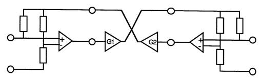
and matrices for each element:
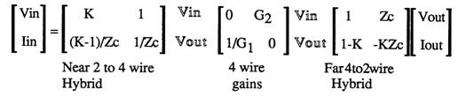
Vout and Vin are the hybrid’s four wire inputs and outputs. The four wire gains matrix connects one hybrid’s Vout to the other hybrid’s Vin. Vout and Vin are intermediate variables and are shown to aid understanding.
These would be multiplied together to form an ABCD matrix.
Note that there is a 6dB loss across the hybrids when driving matched loads. This needs to be allowed for. This again is because of the outputs of G1 and G2 form the EMFs driving the hybrids.
(Note: The AD-BC = 1 reciprocity rule (p262 [8]) does not apply as it does for passive networks so this cannot be used as a rounding error check on the calculations!)
5 Putting a network together
Two telephones and some line make a telephone connection, ignoring the exchange. The circuit below shows the complete network:
Multiplying the matrices together results in:
The use of OLR and STMR allude to the Loudness Ratings. These should be OLR' and STMR'. This is an allusion, as OLR and STMR are calculated at 14 frequencies as defined in ITU P.79.
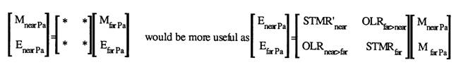
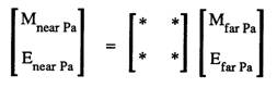
It is evident that the network is in terms of near end microphone and earpiece sound pressures based upon the far end microphone and earpiece sound pressures.
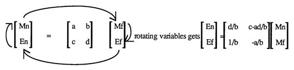
For loudness ratings the acoustics gains (Earpiece pressure/Microphone pressure) are required. By a little rearrangement of variables these can be found.
Below shows that the required function rotates the variables( p264 of [8] expands upon this, but the algebra used to derive the telephone matrix can be used also):

This is useful as it can be used to :
1) Calculated the impedance for zero sidetone for the network,
2) Allows rearrangement of variables to give easy access to the sensitivities.
3) Convert a network into an admittance - parameter network.
4) Application of the function twice allows matrix inversion.
5) Conversion to z parameter matrices.
PROCEDURE convert;
{ This rotates the variables of a two by two matrix clockwise
   [m]=[  ][M]  ==>  [e]=[ ][m]
   [e] [  ][E]       [E] [ ][M] see paper for formulae}

VAR

y11r,y11i,y12r,y12i,y21r,y21i,y22r,y22i,cr,ci:REAL;

BEGIN
  cr:=rbr;ci:=rbi; {calc inverse of b}
  inv(cr,ci);
  {evaluate terms}
  y11r:=rdr;                       y11i:=rdi;
  y12r:=multr(rar,rai,rdr,rdi);    y12i:=multi(rar,rai,rdr,rdi);
  y21r:=1.0;                       y21i:=0.0;
  y22r:=-rar;                      y22i:=-rai;
  {now divide by b and put back}
  rar:=multr(y11r,y11i,cr,ci);      rai:=multi(y11r,y11i,cr,ci);
  rbr:=rcr-multr(y12r,y12i,cr,ci);  rbi:=rci-multi(y12r,y12i,cr,ci);
  rcr:=multr(y21r,y21i,cr,ci);      rci:=multi(y21r,y21i,cr,ci);
  rdr:=multr(y22r,y22i,cr,ci);      rdi:=multi(y22r,y22i,cr,ci);
END; {convert}
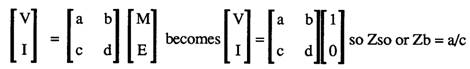
6 Calculating the impedance for zero sidetone
Minimum sidetone is when the earpiece pressure is at a minimum when there is some microphone voltage. So subsituting M=1 and E=0 into the equation below, and then dividing V/l we get the impedance for zero sidetone:
This would be useful with sensitivity analysis software and optimization software to calculate optimum impedences.
7 Rearrangement for easy access to the sensitivities
For PABX evaluation the SLR, RLR and STMR into a stone bridge and 600 ohm source/load is required.
If a series 600 ohm impedance is attached to the near end telephone model then the following sensitivities for the loudness ratings are available as shown below:
rotated to
M and V are "outputs" but are really inputs. The matrices allow E = e M + f V and allow E/M and E/V using super-position.
V is an output relative to M_near and input relative to M_far using super-position. I call this impeadence multiplexing.
7a some considerations
Below is a definition of the two port network and the ABCD parameters.
ABCD Matrix representation.
The Inputs are expressed as a Matrix multiplied by the output.
  PROCEDURE multmat(nar,nai,nbr,nbi,ncr,nci,ndr,ndi:REAL);
  {multiplies the complex two by two matries [r]:=[r]*[n]}
The Inputs are expressed as a Matrix multiplied by the output.
Inputs := [ A ] Outputs.
Append [ B ] to [ A ] where the outputs of A form the inputs of B.
Inputs := [ A ] Outputs.
Inputs := [ B ] Outputs.
So Inputs := [ A ][ B ] Outputs.
If expressed Outputs := [ ] Inputs.
then prepend B for Outputs := [ B ][ A ] Inputs, where the outputs of A form the inputs of B.
Convert() can be used to rotate into correct format.
This models the hybrid inputing 4 wire to 2 wire [ M ] = [ ] [V] see paper on loudness ratings [ E ] [ ] [I] Convert() can be used to rotate the variables around:-
Normally, for Amplifiers, the flow is from input to output. You connect a signal to the inputs.
Normally, for Amplifiers, the flow is from input to output. You connect a signal to the inputs and get an output.
The ABCD matrix is expressed as Inputs based on outputs. You can measure the signal on the inputs and outputs and work out ratios.
You cannot connect a signal generator to the output and expect to see the input signal change.
It makes it easy to chain the blocks together.
Be careful when adding components.
7b Sensitivites
For a phone you need sound pressure ratios, so you need the sensitivites: M V/Pa and E Pa/V
My 2x2 matrices are in terms of E,M,V I, but measuring the voltage of M and E in a real circuit has added complications. There are amplifiers in circuit, and the circuit is inside a case. The shape of the handset affect sensitivities.
So the sensitivities are stated relative to places that are simple to measure, like the plug or terminal strip or junction.
The PABX requirment document had an AnnexA which had tables of sensitivies for " BT700 TYPE TELEPHONE DATA - The following send and receive sensitivites are between MATCHED impedances. Additionally, the receive sensitivity contains an allowance for real ear loss."
Also, it had AnnexB which had tables of sensitivies for " COMPLEX IMPEDANCE TELEPHONE DATA - The following send and receive sensitivites are between MATCHED impedances. "
The table of sensitives for the Microphone states Sensistivites to MATCHED impedances. So M = 2V, and E=V
The table of sensitives for the Earphone states Sensistivites to MATCHED impedances. So E=V
When measuring Earphone states Sensistivites, the presure is measured, and the test signal is V*2.
In the PABX requirements document[10], one set of Earphone Sensistivites includes real ear loss as well!
When measuring RLR, a Signal source, 600ohm impedance is used. The test signal emf, would be V*2 if Zc = 600ohm.
The document could have stated the "generator" EMF, but used MATCHED impedances instead.
So the junction voltage is half the generator voltage, and the exact value of Zc does not need to be known.
This gets complicated. Further reading:-
ITU P.64 : Determination of sensitivity/frequency characteristics of local telephone systems
ITU P.76 : Determination of loudness ratings; fundamental principles
ITU P.79 : Calculation of loudness ratings for telephone sets
7d Other Hybrid circuits
Norton current sources:-
Simplified Phone redrawn from a copy of a real phone circuit. It uses the NORTON configuration.
8 References:
[8] F.F. Kuo, Network Analysis and Synthesis, Wiley International,1962
[9] N.A Pashtoon,Chap 4 of D.F.EIIiott, Handbook of Digital Signal Processing Engineering Applications,Academic Press, 1987
[10] BTR 1050
[11] https://sound-au.com/appnotes/an010.htm - Audio Hybrids for talk shows
[12] https://www.epanorama.net/circuits/teleinterface.html#noisolation - Audio Hybrids
[13] BTR1050
8a References and articles worth reading:
[14] ISBN 0 86341 080 4, Local Telecommunications 2, IEE , page 29, in chapter 2 Voice communications requirements.
[15] p267 British Telecommunications Engineering. Vol 5 Jan 1987
[16] https://sound-au.com/appnotes/an010.htm 2-4 Wire Converters / Hybrids, Rod Elliott (ESP)
[17] http://www.dfrtelecoms.org.uk/dialtele.htm John Bathgate, Dean Forest Railway Telecoms
[18] https://www.epanorama.net/circuits/teleinterface.html#noisolation , Telephone line audio interface circuits, Tomi Engdahl
[19] https://www.itu.int/pub/T-HDB https://www.itu.int/pub/T-HDB-MES.2-1993 Handbook on Telephonometry
[20] https://www.digitalarchives.bt.com/Calmview/ BT has the research reports
[21] https://www.digitalarchives.bt.com/CalmView/GetDocument.ashx?db=Catalog&fname=TCC_23%2fBT_Archives_TCC_23_630.pdf Computation of the Characteristics of Telephone Connections, PK Webb
9 The Turbo Pascal code:-
The Turbo Pascal code for this is:
{----------------------------------------------------------------}

{
//// 6.6 ABCD MATRIX CALCULATION FUNCTIONS
}

{The next set of procedures and functions are
used to evaluate the voltage ratios.
They are collection of two by two matrix manipulation routines - see paper on
calculation of loudness ratings}

FUNCTION multr(rar,rai,rbr,rbi:REAL):REAL;
{returns the real part of a matrix multiplication}
BEGIN
  multr:=rar*rbr-rai*rbi;
END;

FUNCTION multi(rar,rai,rbr,rbi:REAL):REAL;
{returns the imag part of a matrix multiplication}
BEGIN
  multi:=rar*rbi+rai*rbr;
END;


PROCEDURE multmat(nar,nai,nbr,nbi,ncr,nci,ndr,ndi:REAL);
{multiplies the complex two by two matries [r]:=[r]*[n]}
BEGIN
  ar:=rar;ai:=rai;
  br:=rbr;bi:=rbi;
  cr:=rcr;ci:=rci;
  dr:=rdr;di:=rdi;

  rar:=ar*nar-ai*nai+br*ncr-bi*nci;
  rai:=ar*nai+ai*nar+br*nci+bi*ncr;

  rbr:=ar*nbr-ai*nbi+br*ndr-bi*ndi;
  rbi:=ar*nbi+ai*nbr+br*ndi+bi*ndr;

  rcr:=cr*nar-ci*nai+dr*ncr-di*nci;
  rci:=cr*nai+ci*nar+dr*nci+di*ncr;

  rdr:=cr*nbr-ci*nbi+dr*ndr-di*ndi;
  rdi:=cr*nbi+ci*nbr+dr*ndi+di*ndr;

END;  {multmat}

PROCEDURE multabcd(nbr,nbi,ncr,nci:REAL);
{as multmat except n matrix = [1 b] to reduce the number of parameters
                              [c 1]
 intended for simple parrallel of series components }

CONST nar=1;nai=0;
      ndr=1;ndi=0;

BEGIN
  multmat(nar,nai,nbr,nbi,ncr,nci,ndr,ndi);
END;{multabcd}

PROCEDURE multy(yr,yi:REAL);
{multiplies parrallel admmitance}
BEGIN
  multabcd(0,0,yr,yi);
END;

PROCEDURE  multz(zr,zi:REAL);
{multiples series impedance }
BEGIN
  multabcd(zr,zi,0,0);
END;

PROCEDURE inv(VAR xr,xi:REAL);
{ does complex 1/x }
VAR

 d:REAL;

BEGIN
  d:=xr*xr+xi*xi;
  xr:=xr/d;
  xi:=-xi/d;
END;{inv}

{
//// 6.7 4-2 WIRE HYBRID MATRIX CALCULATION FUNCTIONS
}

PROCEDURE calk(VAR yr,yi:REAL; zcr,zci,zbr,zbi:REAL);
{calculates complex zb/(zb+zc) }
VAR
 t,d:REAL;
BEGIN
  inv(zbr,zbi);
  yr:=zcr*zbr-zci*zbi;
  yi:=zcr*zbi+zci*zbr;
  yr:=1+yr;
  inv(yr,yi);
END; {calk}

PROCEDURE twoto4(zcr,zci,zbr,zbi:REAL);
{This models the hybrid inputing 4 wire to 2 wire [ M ] = [   ] [V]
see paper on loudness ratings                     [ E ]   [   ] [I]  }

VAR

ar,ai,br,bi,cr,ci,dr,di:REAL;

BEGIN
  ar:=0.5;ai:=0;
  br:=zcr/2;bi:=zci/2;
  calk(cr,ci,zcr,zci,zbr,zbi);
  dr:=-(cr*zcr-ci*zci);
  di:=-(cr*zci+ci*zcr);
  cr:=1-cr;ci:=-ci;
  multmat(ar,ai,br,bi,cr,ci,dr,di);
END; {twoto4}

PROCEDURE fourto2(zcr,zci,zbr,zbi:REAL);

{This models the hybrid inputing 2 wire to 4 wire [ V ] = [   ] [ M ]
                                                  [ I ]   [   ] [ E ]  }

VAR

ar,ai,br,bi,cr,ci,dr,di:REAL;

BEGIN
  calk(ar,ai,zcr,zci,zbr,zbi);
  inv(zcr,zci);
  br:=1;bi:=0;
  dr:=zcr;di:=zci;
  cr:=((ar-1)*zcr-ai*zci)*2;
  ci:=((ar-1)*zci+ai*zcr)*2;
  ar:=ar*2;ai:=ai*2;
  multmat(ar,ai,br,bi,cr,ci,dr,di);
END; {fourto2}

PROCEDURE convert;
{ This rotates the variables of a two by two matrix clockwise
   [m]=[  ][M]  ==>  [e]=[ ][m]
   [e] [  ][E]       [E] [ ][M] see paper for formulae}

VAR

y11r,y11i,y12r,y12i,y21r,y21i,y22r,y22i,cr,ci:REAL;

BEGIN
  cr:=rbr;ci:=rbi; {calc inverse of b}
  inv(cr,ci);
  {evaluate terms}
  y11r:=rdr;                       y11i:=rdi;
  y12r:=multr(rar,rai,rdr,rdi);    y12i:=multi(rar,rai,rdr,rdi);
  y21r:=1.0;                       y21i:=0.0;
  y22r:=-rar;                      y22i:=-rai;
  {now divide by b and put back}
  rar:=multr(y11r,y11i,cr,ci);      rai:=multi(y11r,y11i,cr,ci);
  rbr:=rcr-multr(y12r,y12i,cr,ci);  rbi:=rci-multi(y12r,y12i,cr,ci);
  rcr:=multr(y21r,y21i,cr,ci);      rci:=multi(y21r,y21i,cr,ci);
  rdr:=multr(y22r,y22i,cr,ci);      rdi:=multi(y22r,y22i,cr,ci);
END; {convert}

PROCEDURE fwgains(lfr,lfi,gnr,gni:REAL);
{This procedure applies the gains for four wires circuits
   [ 0      lf>n]
   [ gn>f   0   ] }

VAR

ar,ai,br,bi:REAL;

BEGIN
  multmat(0.0,0.0,lfr,lfi,gnr,gni,0.0,0.0);
END; {fwgains}

{
//// 6.8 ARTIFICIAL LINES MATRIX CALCULATION FUNCTIONS
}
PROCEDURE lines (length : REAL);
{ This procedure evaluates line sections for unloaded line.
  The model is that of BTR 1050
  Operation is akin to long multipliction , 100 meter sections
  are conditionally added}

VAR

                     len,il,il2 : INTEGER;
aar,aai,abr,abi,acr,aci,aqr,aqi : REAL;


BEGIN
  len:=ROUND(length*10);{length is km of line}
  IF len <> 0 THEN
  BEGIN
    il:=0;
    il2:=1;
    aar:=rar;   aai:=rai;
    abr:=rbr;   abi:=rbi;
    acr:=rcr;   aci:=rci;
    aqr:=rdr;   aqi:=rdi;
    rar:=1;      rai:=0;
    rbr:=0;      rbi:=0;
    rcr:=0;      rci:=0;
    rdr:=1;      rdi:=0;

   {100 metre section = O---[===]----O
                          I       I
                         ===     ===  2.5nF
                          I       I
                        O---[===]----O
                             16.8 ohm         }

    multy(0,w*2.5E-9);
    multz(16.8,0);
    multy(0,w*2.5E-9);
    WHILE len > 0 DO
    BEGIN
      IF (len-2*(len DIV 2))=1 THEN
      BEGIN
        ar:=aar;  ai:=aai;
        br:=abr;  bi:=abi;
        cr:=acr;  ci:=aci;
        dr:=aqr;  di:=aqi;

        aar:=ar*rar-ai*rai+br*rcr-bi*rci;
        aai:=ar*rai+ai*rar+br*rci+bi*rcr;

        abr:=ar*rbr-ai*rbi+br*rdr-bi*rdi;
        abi:=ar*rbi+ai*rbr+br*rdi+bi*rdr;

        acr:=cr*rar-ci*rai+dr*rcr-di*rci;
        aci:=cr*rai+ci*rar+dr*rci+di*rcr;

        aqr:=cr*rbr-ci*rbi+dr*rdr-di*rdi;
        aqi:=cr*rbi+ci*rbr+dr*rdi+di*rdr;

        il:=il+il2
      END;
      multmat (rar,rai,rbr,rbi,rcr,rci,rdr,rdi);
      il2:=il2+il2;
      len:=len DIV 2
    END;
    rar:=aar;   rai:=aai;
    rbr:=abr;   rbi:=abi;
    rcr:=acr;   rci:=aci;
    rdr:=aqr;   rdi:=aqi;
  END
END; {line}

{
//// 6.9 COMPLETE CONNECTION CALCULATION FUNCTIONS
}

PROCEDURE throughcalc (length1,length2 : REAL);
{throughcalc exercises a connection for different length lines
It calcultes the voltage ratios for the three connection types supported,
then uses these to calculate the loudness ratings }


VAR

c : INTEGER;
k1,k2,k3,zlr,zli:REAL;
Le,SrLeN,SrLeF,SMJ,SJE,LMe,LMeST,m:REAL;

BEGIN
olrNF:=0.0;
olrFN:=0.0;

rlr:=0.0;
slr:=0.0;

stmrN:=0.0;
stmrF:=0.0;

LMeST:=0.0;

k:=1;
FOR c:= 0 TO 13 DO BEGIN
   w:=freq[c]*2*pi;
   rar:=1.0;rai:=0.0;
   rbr:=0.0;rbi:=0.0;
   rcr:=0.0;rci:=0.0;
   rdr:=1.0;rdi:=0.0;

   twoto4(phonestore[near,c,zcr],phonestore[near,c,zci],
      phonestore[near,c,zbr],phonestore[near,c,zbi]);  {near phone hybrid}
   lines(length1);                                     { line  }
   fourto2(work[c,0],work[c,1],work[c,2],work[c,3]);   {exchange hybrid}
   fwgains(work[c,8],work[c,9],work[c,10],work[c,11]); {gains}
   twoto4(work[c,4],work[c,5],work[c,6],work[c,7]);    {exchange hybrid}
   lines(length2);                                     {line   }
   { choice of phone   to phone
                       to  to 600 ohm
                           to stonebridge and 600ohm
   }

   { For BT700 phone data sr includes RealEarLoss, for COMPLEX phone data sr does does not include Real Ear loss }
   { LMe and LMeST should not include Real Ear Loss. 'e' means Artifical Ear }
   Le    := leA[ c ];

   SrLeN := Le;
   SrLeF := Le;
   { removedRealEarLoss when loading BT700 phone data }
   SrLeN := 0.0;
   SrLeF := 0.0;


   IF ct = 'p' THEN BEGIN {phone to phone option }
      fourto2(phonestore[far,c,zcr],phonestore[far,c,zci],
         phonestore[far,c,zbr],phonestore[far,c,zbi]);{far phone hybrid}

      convert;{convert from 'ABCD' format to 'E =[r] M' format [r]= [a b ]
                                                                    [c d ] }

      (* olr k's= calculated loss in volts *)
      k:=rbr*rbr+rbi*rbi;        {b= EN/MF}
      { m:=0.0175*(10.0*LN(k)/ln10-wo[c]+phonestore[far,c,ss]+phonestore[near,c,sr]); }
      LMe  := -( 10.0*LN(k)/ln10 +phonestore[far,c,ss]  + phonestore[near,c,sr] + SrLeN );
      m:= 0.0175*( -LMe -Le -wo[c] );
      olrFN:=olrFN + exp( m*ln10 );

      k:=rcr*rcr+rci*rci;    {c= EF/MN}
      { m:=0.0175*(10.0*LN(k)/ln10-wo[c]+phonestore[near,c,ss]+phonestore[far,c,sr]); }
      LMe  := -( 10.0*LN(k)/ln10 +phonestore[near,c,ss]  + phonestore[far,c,sr] + SrLeF );
      m:= 0.0175*( -LMe -Le -wo[c] );
      olrNF:=olrNF + exp( m*ln10 );

      (*stmr k's= calculated loss in volts *)
      k:=rar*rar+rai*rai;   {a= EN/MN}
      { m:=0.0225*(10.0*LN(k)/ln10-wm[c]+phonestore[near,c,ss]+phonestore[near,c,sr]); }
      LMeST:= -( 10.0*LN(k)/ln10 +phonestore[near,c,ss]+phonestore[near,c,sr]+SrLeN );
      m:=0.0225*( -LMeST -Le -wm[c] );
      stmrN:=stmrN+exp(m*ln10);
      write( 'LMeST: ', LMeST:8:2 );


      k:=rdr*rdr+rdi*rdi;                             {d= EF/MF}
      { m:=0.0225*(10.0*LN(k)/ln10-wm[c]+phonestore[far,c,ss]+phonestore[far,c,sr]);}
      LMeST:= -(   10.0*LN(k)/ln10 +phonestore[far,c,ss]+phonestore[far,c,sr]+SrLeF );
      m:=0.0225*( -LMeST -Le -wm[c] );
      stmrF:=stmrF+exp(m*ln10);
      writeln( ' LMeST: ', LMeST:8:2 );

   END
ELSE BEGIN           {phone to trunk option }
   IF ct='t' THEN BEGIN { a stone bridge is inserted
                         ( see BS 6317 ammendments)}
      zlr:=400;zli:=w*3;{inductors are total of 400 ohm + 3 H}
      inv(zlr,zli);
      multy(zlr,zli);     {stone bridge inductors};
      multz(0,-1/(w*1.0E-6));{ the capacitors(1uF)};     {M = [  ]V}
      multy(zlr,zli);
   END;
   multy(+1/600,0);      {Interface };          {E = [  ]I}
   k1:=rar*rar+rai*rai;     {a=M/V}
   {   k:=0.0175*(-10.0*ln(k1)/ln10-ws[c]+phonestore[near,c,ss]); }
   SMJ := -10.0*ln(k1)/ln10+phonestore[near,c,ss];
   k:=0.0175*( SMJ-ws[c]);
   slr:=slr+exp(k*ln10);

   write( ' SMJ: ', SMJ:8:2 );


   multy(-1/600,0);      {take off 600 ohm load and add 600 ohm V generator}
   multz(600,0);
   convert;              {convert to this format E=[  ]M}

   k2:=rbr*rbr+rbi*rbi;  {b=E/V}   {       I=[  ]V}
   {  k:=0.0175*(10.0*ln(k2*4)/ln10-wr[c]+phonestore[near,c,sr]); }
   {k2=E*E/V*V want e/(v/2)}
   SJE:= 10.0*ln(k2*4)/ln10+phonestore[near,c,sr] +SrLeN;
   k:=0.0175*( SJE -Le- wr[c]);
      {k2=E*E/V*V want e/(v/2)}

   rlr:=rlr+exp(k*ln10);
   write( ' SJE: ', SJE:8:2 );


   k1:=rar*rar+rai*rai;    {a=E/M }
{  k:=0.0225*(10.0*ln(k1)/ln10-wm[c]+phonestore[near,c,ss] +phonestore[near,c,sr]); }
   LMeST := -(10.0*ln(k1)/ln10 + phonestore[near,c,ss] +phonestore[near,c,sr] +SrLeN );
   k:=0.0225*( -LMeST -Le -wm[c] );
   stmrN:=stmrN+exp(k*ln10);
   writeln( ' LMeST: ', LMeST:8:2 );

   END;
END;

IF ct='p' THEN BEGIN
   olrNF:=-1/0.0175*ln(olrNF)/ln10;
   olrFN:=-1/0.0175*ln(olrFN)/ln10;
   stmrN:=-1/0.0225*ln(stmrN)/ln10;
   stmrF:=-1/0.0225*ln(stmrF)/ln10;

END
ELSE BEGIN  {do 't' or '6'}
   slr  :=-1/0.0175*ln(slr)/ln10;
   rlr  :=-1/0.0175*ln(rlr)/ln10;
   stmrN:=-1/0.0225*ln(stmrN)/ln10;
END;

resultscreen(length1,length2);
END;{throughcalc}

PROCEDURE loopcontrol;
{ This execises the connection for different length lines }
VAR

   l1,l2,cc : INTEGER;
      length:real;
      escape:boolean;

BEGIN
  escape := FALSE;
  with linlen[1] do
  BEGIN {with}
    length:=from;
    while (length < too ) and not escape do
    BEGIN
      throughcalc(fixed,length);
      length:=length + step;
      escape := check_escape;
    END;
  END;  {with}
  with linlen[2] do
  BEGIN {with}
    length:=from;
    while ( length < too ) and not escape do
    BEGIN
      throughcalc(length,fixed);
      length:=length + step;
      escape := check_escape;
    END;
  END;  {with}
  with linlen[3] do
  BEGIN  {with}
    length:=from;
    while ( length < too ) and not escape do
    BEGIN
      throughcalc(length,length);
      length:=length + step;
      escape := check_escape;

    END;
  END;   {with}
END;{loopcontrol}
Updated calculations to match the formulae
Updated LR calculations, that follow the presented formulae.
The matrices work out voltages on the idea Microphone M and idea earphone E
However the phone sensitivities are relative to V, the voltage on the two wire interface.
For some phone data there is a statement:-
The send and receive sensitivites are between MATCHED impedances. This means M= 2*V, and E=V
Some also have:- "additionally, the receive sensitivities contain an allowance for Real Ear Loss" , so SrLe should be set to Le or 0.0, as required.
   IF ct = 'p' THEN BEGIN {phone to phone option }
      fourto2(phonestore[far,c,zcr],phonestore[far,c,zci],
      phonestore[far,c,zbr],phonestore[far,c,zbi]);{far phone hybrid}

      convert;{convert from 'ABCD' format to 'E =[r] M' format [r]= [a b ]
                                                                    [c d ] }
      (* olr k's= calculated loss in volts *)
      k:=rbr*rbr+rbi*rbi;

      { (* b= EN/MF *)  }


      LMe  := -( 10.0*LN(k)/ln10 +phonestore[far,c,ss]  + phonestore[near,c,sr]  );
      m:= 0.0175*( -LMe -Le -wo[c] );
      olrFN:=olrFN + exp( m*ln10 );

      k:=rcr*rcr+rci*rci; (* {c= EF/MN} *)
      LMe := -( 10.0*LN(k)/ln10   +phonestore[near,c,ss] + phonestore[far,c,sr]  );
      m   :=0.0175*( -LMe  -Le -wo[ c ] );
      olrNF:=olrNF+exp(m*ln10);


      (*stmr k's= calculated loss in volts *)
      k:=rar*rar+rai*rai;  {a= EN/MN}
      LMeST:= -( 10.0*LN(k)/ln10 +phonestore[near,c,ss]+phonestore[near,c,sr] );
      m:=0.0225*( -LMeST -Le -wm[c] );
      stmrNear:=stmrNear+exp(m*ln10);
      write( 'LMeST: ', LMeST:8:2 );

      k:=rdr*rdr+rdi*rdi;                             {d= EF/MF}
      LMeST:= -(   10.0*LN(k)/ln10 +phonestore[far,c,ss]+phonestore[far,c,sr] );
      m:=0.0225*( -LMeST -Le -wm[c] );
      stmrFar:=stmrFar+exp(m*ln10);
      writeln( ' LMeST: ', LMeST:8:2 );
   END
The loudness ratings need to be finally worked out. The variables were used for the sum, and then finally for the loudness rating.
   olrNF:=-1/0.0175*ln( olrNF )/ln10;
   olrFN:=-1/0.0175*ln( olrFN )/ln10;

   stmrNear:=-1/0.0225*ln(stmrNear)/ln10;
   stmrFar:=-1/0.0225*ln(stmrFar)/ln10;
The formulae from the PABX spec.
The PABX spec had these formulae. Also published in ISBN 0 86341 080 4, Local Telecommunications 2, IEE , page 29, in chapter 2 Voice communications requirements.
	SLR = (-1/0.0175) * log10( sumFor14freqs( 10^(0.0175 ( SMJ-WS ) ) )

	RLR = (-1/0.0175) * log10( sumFor14freqs( 10^(0.0175 ( SJe-LE-WR ) ) )

	OLR = (-1/0.0175) * log10( sumFor14freqs( 10^(0.0175 ( -LMe-LE-WO ) ) )

	STMR = (-1/0.0225) * log10( sumFor14freqs( 10^(0.0225 ( -LMeST-LE-WM ) ) )
Where:-
	SMJ is the sending electroacoustic sensitivity of the telephone circuit

	SMJ = 20 log10( Voltage across the 600 ohm Termination / Sound pressure at the Mouth Reference point ) dB rel 1V/Pa


	SJe is the receiving  electroacoustic sensitivity of the telephone circuit, where the 600 Ohm termination is replaced by a 600 ohm oscillator of EMF E volts.

	SJe = 20 log10( Sound pressure level in the artificial Ear / ( E /2 )   ) dB rel Pa / V


	LMe is the overall electro acoustic loss of the telephone circuit. It includes Exchange Line, Stone bridge and 600 Ohm termination with an extension telephone and line.

        (GEN)- [ 600 Ohm ] - [ stone bridge ] - [ line ] - [ PABX ] - [ line ] - [ Phone ]

	LMe = 20 log10( Sound pressure at the Mouth Reference point  / Sound pressure level in the artificial Ear  ) dB


	LMeST is the electro acoustic loss of the sidetone path

	LMeST = 20 log10( Sound pressure at the Mouth Reference point  / Sound pressure level in the artificial Ear  ) dB

	The lowercase 'e' in SJe, LMe, and LMeST denotes values using an artificial ear.

	A stone bridge isolates the DC , and used 2uF capacitors and relays to feed current via (1.5H +200 Ohm) from the battery.
Conclusion
Using the 2x2 matrices and other functions, the telephone connections can be explored.
Copyright Douglas Rice, doug.h.rice@btinternet.com , 2005,2008,2023