This is a bit of a challenge. My Original design original design used a PIC16F84, and was relatively easy to use and quite simple in function.
I decided to port my design to an 8 pin device, to make it smaller.
I do not have the ability to use custom LCD displays or use surface mount devices, so the design is limited to an 8 pin PIC12F675, using one button and LED and a sounder.
So here is a design. It is still not perfect, and much more complicated than it seems.
The timer built into a window alarm.
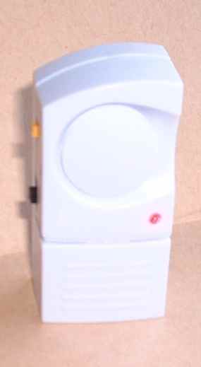
The timer built into a window alarm. Internals
The user is expected to set up the cassette recorder and radio to record Radio 4 as you would if you were to record it live. Use the button to toggle turn off the power.The original design turns on the radio cassette recorder when the Shipping forecast is broadcast.
However, you need to be able to set the time.
The original design allowed the user to set the time by use of two buttons, NEXT and SET.
You use NEXT to toggle on and off. The SET button is recessed and used to enter the Time Setting mode.
To set the time, enter the time setting mode and enter the time HH:MM by entering each digit in sequence. Use the SET button to increment the digit, and NEXT to move onto the next digit. Finally, use the SET button to confirm the new time and set the timer at HH:MM:45.
To read the time, beep out the time as the time is being set and then do not bother to confirm the entered time.
I decided to use one button and still use the beeps and LED. NEXT is done by a dab of the button and SET is done by a longer press.
This is quite easy to do, but turns out to be very difficult to use.
The functions for the timer were:
Turn the cassette power on while the shipping forecast was being broadcast.
The user to review the time
The user to set the time
The user to update the on off times stored in the EEPROM
The original design had the following inputs.
NEXT button
SET button
Serial Input
The outputs were:
Key Click LED
BEEP LED
Serial Out
Relay Control Output
Bicolour LED – Red
Bicolour LED - Green
Audio Out for beeps
Not all of these had their own pins.
The original time used Bi-coloured LEDs and injected a beep into the radio.
Each digit was beeped out using the format.
0
1 .
2 .
3 ...
4 ....
5 .... _
6 .... _ .
7 .... _ ..
8 .... _ ...
9 .... _ ....
I had to introduce the use of the beeper and key clicks.
A short press toggles the power and does teh NEXT function, an long press enteres time setting mode and does the SET function. I added a very long press and you get to the time read out mode.
When you press the button, you hear a click. As you hold it down you get another click and then another. Release between clicks to select the function.
=======
Buttons
=======

One button can be on or off.

If it is on, it can only change to off.
If it is off, it can only change to on.

It is impossible to provide a choice of future.

For a menu, you need two buttons: Next,Enter

With one button, you need to use time as well to qualify pressing.

You need feedback to indicate that the timer has matured.

Next could be a short press
Enter could be a long press
It is good to have a reset/abort as well.
Abort could be a very long press to jump out of the menu.


=======================
Timers are interesting.
=======================

Timers can time out at a constant rate.
Timers can be started by an event, and they time out.
Timers can be restarted by an event, and they time out.

Timers can time between events, and the time used to qualify the time.

A button can toggle from off to on, and then from on to off.

This means that there is loads of choice.

Using the least amount of conditioning, how many descreate symbols are generated.
Using a timer that triggers on a toggle, is there a toggle
before or after the next timeout?

This allows a single button to choose a future.
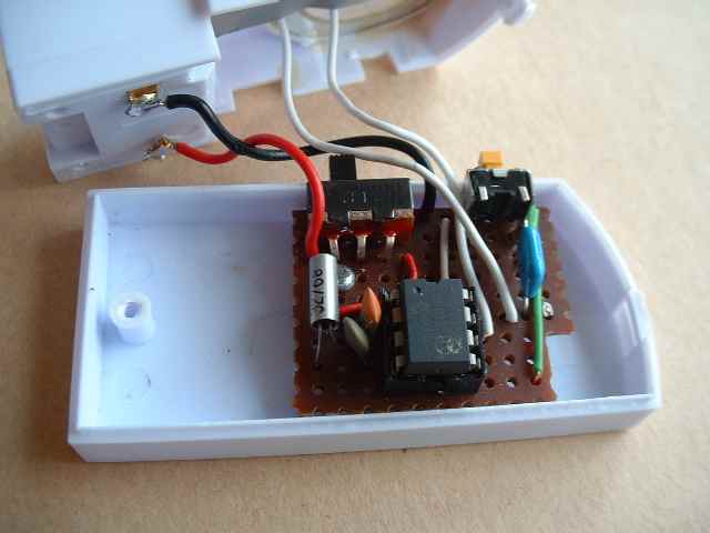
The timer built into a window alarm.
The timer built into a window alarm. Internals