Updates to use the 12F683 as well as the 12F675 have been added to the zip file. The 12F683 has a CCP module.
==============================
ReadMe.txt
==============================
Doug Rice copyright, 10th October 2016
==============================

The files in this zip file are experiments in using an 8 pin PIC to measure frequency, period and events.

fc002.asm	- measure frequency, output serial.
fc003.asm	- measure period,    output serial.
fc004.asm	- event logger,      output timestamp of event over serial.

fc005_compare.asm	- signal generator demo using CCP compare. ( not in zipp file )
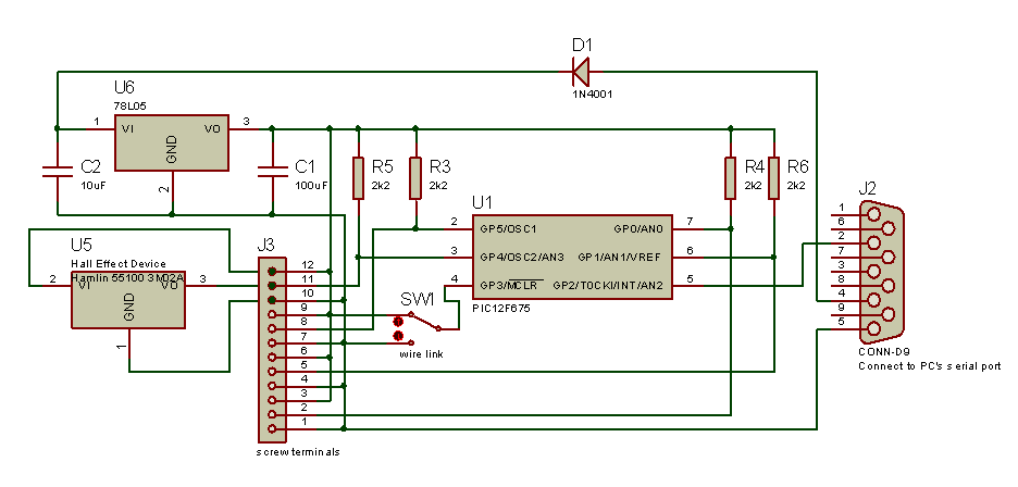
Here is a design for a single chip frequency counter. My LogiPic had a frequency counter in it. Here the code has been used in an 8 pin micro, the Microchip 12F675. These cost less than 2 pounds.
It is possible to use the internal RC oscillator, instead of the crystal but the accuracy suffers.
The counter uses the 8 bit counter TMR0. The main loop samples the timer value, subtracts the sample from the last sample and adds the difference to a count. This is done over exactly 2 seconds, done by counting processor cycles, in a loop that cannot be interrupted. TMR0 is configured so that the input is divided by two.
The binary count is converted to BCD and this is output serially at 1200 baud.
GP3 controls if the comparator is used to pre-amplify the signal. if GP3 is high, then GP2 is Freq counter input. if GP3 is low, then GP1 is Freq counter input. It uses the Comparator and Vref set to about 1 volt.
Why serial? With only 8 pins, it is not possible to connect an LCD display using a parallel interface, and my serial LCD works quite well at 1200 baud.
You could use a serial terminal on a PC to capture the frequency.
Code: - freqMeterCode.zip
;**********************************************************
;*  fc002.asm
;**********************************************************
;*  This program configures a PIC 12F675 to measure the frequency
;* 	Set up the comparator and Vref for the freq input
;*
;*	Analogue input = GP1
;*    test input, GP3,
;*		if GP3 is high, then GP2 is Freq counter input.
;*		if GP3 is low,  then GP1 is Freq counter input. It uses the Comparator and Vref set to about 1 volt.
;*
;*	The frequency is measured other a two second period.
;*	The frequency to be measured clocks the TMR0 divided by two over exactly 2 seconds timed by cycle counting.
;*
;*	For each sample the amount that TMR0 has incremented in at worst 30 cycles.
;*
;*	This means that the max frequency is 256 cycles in 30 uSec = 256 Mhz / 30  = 8.5 Mhz max
;*
;*	I have not tried this counter above 115 Khz, with and oscillator.
;*
;*
;*
;* 	The prescaler is set to divide by 2. I have seen PIC frequency counters rated to 50 MHz
;*
;*	Connect GP0 direct to the serial input of your PC set to 1200 baud.
;*
;*	It outputs f(0,0A,00116074,0);
;* 		where the 2nd Paramter in the state of the GPIO,
;*		and the 3rd parameter is the frequency in decimal hertz.
;*
;*  Copyright 2005, Douglas Rice
;*
;*
;**********************************************************
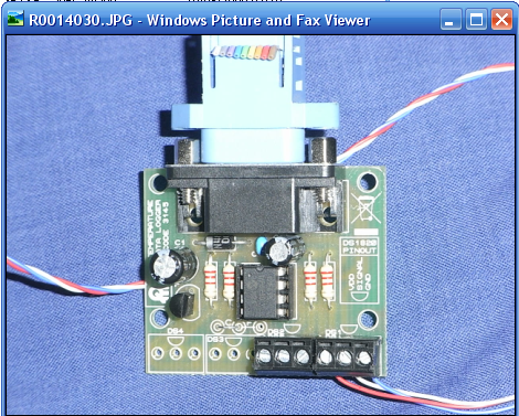
It is possible to rechip the Re chipping the Quasar Temperature logger kit
The code has been changed to use TMR1 on Pin2 and send RS232 to GP2, to suit the kit.
The circuit. 3145 - DS18S20 Computer Serial Temperature Data Logger connected to Hall effect device.
And here connected to a Hall Effect device to count the frequency of the make and breaks.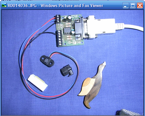
It uses this code. FreqMeterCodeQuasarHallEffect4800Baud.zip
Updates to use the 12F683 as well as the 12F675 have been added to the zip file.
==============================
ReadMe.txt
==============================
Doug Rice copyright, 10th October 2016
==============================

The files in this zip file are experiments in using an 8 pin PIC to measure frequency, period and events.

fc002.asm	- measure frequency, output serial.
fc003.asm	- measure period,    output serial.
fc004.asm	- event logger,      output timestamp of event over serial.
Updates to use the 12F683 as well as the 12F675 have been added to the zip file. The 12F683 has a CCP module.
Code to use this as an event logger, outputting a timestamp in units of 0.4us has been added. Clocking the 12F683 using a sinewave signal generator @ 10dBm has been tried. The PIC is configured in XT mode to give more sensitivity.
Code: - freqMeterCode.zip
;**********************************************************
;*  Event logger:-
;*
;*              +-----------------------+
;*   10MHz/4->--+ 2   TMR1 +16 bit      + --> TMR1IF
;*              +-----------------------+
;*                       |
;*              +-----------------------+
;*   event  ->--+ 5  CCP  32bit Capture +
;*              +-----------------------+
;*                       |
;*                       | on CCPIF event
;*                       |
;*              +-----------------------+
;*              +       bin >BCD        +
;*              +-----------------------+
;*                       |
;*              +-----------------------+
;*              +     Serial            + --> 19200 baud RS232 ->Pin2
;*              +-----------------------+
;*
;**********************************************************
;*  This code uses the Microchip 12F683 to timestamp an event.
;*
;*  The CCP module is configured to take a time stamp on the rising edge of the event signal connected to Pin 5.
;*
;*  The time stamp, in units of 0.4us, is output at 19200 baud on pin 7. This connects to the RS232 rx pin, pin 2 of 9pin connector.
;*
;*	The time stamps are 32bits so range from 0 to 2^32 or  0 to 4294967296.
;*
;*	The time stamp rolls over after 2^32/2500000 seconds = 1717.9869184 seconds = 28.633115306666666666666666666667 minutes
;*
;*  The chip is clocked at 10Mhz.
;*  By using the XT oscillator mode, the OSC 1 pin can be driven by a Frequency standard with a sinewave 10dBm output.
;*
;*  TMR1 clocks at Fosc/4 or 2.5Mhz. This is a 16 bit counter.
;*  When TMR1 overflows it increments another 16 Bit counter.
;*  This provides a time stamp between 0 to 2^32 or 0 to 4294967296.
;*
;**********************************************************
;* Example output:-
;*
;* event 0.4us
;*
;* 0031229812
;* 0031279812
;* 0031329812
;* 0031379812
;* 0031429812
;* 0031479812
;**********************************************************
;* Example of captured output converted to difference, Milleseconds and Frequence using a spreadsheet.
;*
;*  Use the formulae below to get the difference
;*  =+B9-B8
;*
;*  Use the formulae below to convert the difference to milli seconds
;*  =+C9/2500
;*
;* CCP	      delta CCP	ms	    Hz
;*======================================
;* 3339022700
;* 3339072700	50000	20	    50
;* 3339122701	50001	20.0004	49.99900002
;* 3339172701	50000	20	    50
;* 3339222701	50000	20	    50
;* 3339272701	50000	20	    50
;* 3339322701	50000	20	    50
;*
;**********************************************************
;*  See a similar device, the PICPET (  http://www.leapsecond.com/pic/picpet.htm )
;*
;*	The PIC PET is an event logger, It outputs a time stamp between 0 and 100 seconds. in 0.4us steps.
;*
;*  Limitations:-
;*  The time to output the time stamp is about 10 ms, so the events need to be greater than 10ms apart. Keep the event rate less than 100Hz.
;*
;*  Copyright 2005,2016 Douglas Rice
;*
;*  http://www.dougrice.plus.com/hp/freqCounter/freqCounter.html
;*
;**********************************************************
fc005_compare.asm
;**********************************************************
;*  fc005_compare.asm - CCP Compare tryout to generate a waveform.
;*  modified from fc004.asm - Event Logger
;*
;*	It does not do anything except demo CCP compare mode.
;*
;*  Author: Doug Rice
;*  Copyright 2018
;*
;*  Description:
;*
;*	Set up CCP for compare
;*  Turn on TMR1 to increment, do not touch it once running to ensure stable count.
;*  if you start and stop TMR1 and do TMR1 += constant,
;*  the prescaler tend to be reset on write and add jitter.
;*
;*  the CCP compare reduces processing jitter.
;*
;*  Toggle the CCP compare mode to toggle between SET and CLEAR of the CCP pin.
;*
;*  If you use the prescale.
;*
;*  You have to set CCPR1 so that TMR1 has to catch up.
;*
;*  CCPR1 += TMR1ticksToNextMatch
;*
;*	In service routing,  increment CCPR1 by different amounts for Hi and Low
;*  CCPR1 has to be set to ahead or TMR1 so TMR1 catches up
;*
;*  To see the software jitter, toggle another output in the service routine so that the software jitter can be seen.
;*
;*  On first compare copy TMR1 to CCPR1 and add increment.
;*
;*
;*  ideas:-
;*  with CCP pin set to output, capture TMR1 by changing the mode to capture and changing pin level.
;*  Not sure what happens if pin is output and CCP is in Capture mode - it triggers a capture.
;*  convert to compare mode to set CCP pin.
;*  Now Add timeout to CCP
;*  Let it time out
;*  convert to compare mode to CLEAR CCP pin.
;*  Now Add next timeout to CCP
;*  Let it time out

;**********************************************************
;*
;*  Copyright 2018 Douglas Rice
;*
;*  http://www.dougrice.plus.com/hp/freqCounter/freqCounter.html
;*
;**********************************************************
;*
;* Modify this to use compare.
;*
;* init
;*   TMR1 started
;*   CCP set up for compare.
;*
;* while(1){
;*
;*   wait for TMRR1 == CCPH
;*   toggle mode so output toggles.
;*   increment CCPR1H so it is ahead of TMR1. TMR1 catches up and in ISR increment CCPR1 by required timeout.
;*
;*   Note: use modulo 2^16 in TMR1 and CCPH to keep TMR1 < CCPH
;*}
;*
;*
;* 12F683 pins
;	1 U 8
;	2   7
;	3   6
;	4   5

;Pins for 12F683
;1	VDD
;2	GP5/TICKI/OSC1/CLKIN
;2	GP4/AN3/TIG/OSC2/CLKOUT
;4	GP3/MCLR/VPP
;
;8	VSS
;7	GP0/AN0/CIN+/ICSPDAT/ULPWU
;6	GP1/AN1/CIN-/VREF/ICSPCLK
;5	GP2/AN2/T0CKI/INT/COUT/CCP1
;*
;
;**********************************************************