Modeling Telephony Hybrids using 2 x 2 Matrices
Author: Douglas Rice
2 ABCD Parameter basics
ABCD parameters are a method of characterising a two-port network in terms of the input and output voltages and currents. They are used as the matrices that contain them can be chained together like the bits in a telephone network that they model.
On this web page all voltages, currents, pressures and sensitivities are in linear, complex number (a+jb) representation unless dB is explicitly mentioned.
Below is a definition of the two port network and the ABCD parameters.
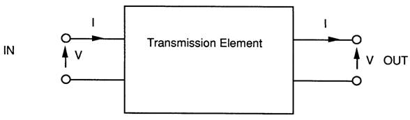
ABCD Matrix representation.
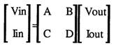
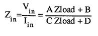
Once a program has been written to chain these together the impedance looking into the network can be calculated as shown below:
Zin=Vin/lin and Vout = ZIoad * lout.
so:
3 The 2*2 Matrix model of a telephone
If a model for a telephone can be written down as a 2 by 2 matrix then the same program can be used to multiply the matrices together and calculate the telephone performance.
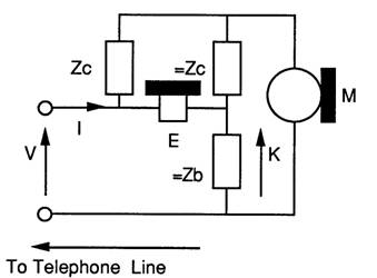
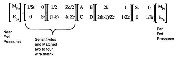
As far as the transmission is concerned the 2 wire telephone is in essence is a Wheatstone bridge. The line is the unknown impedance, the microphone is the generator and the earpiece is the detector. The diagram below shows the circuit:
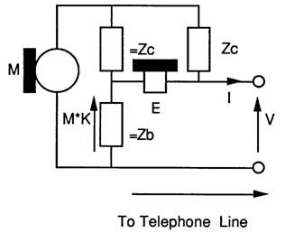
It is important to understand the following salient points about the components.
The microphone is a ideal voltage source, and so it has zero impedance.
The earpiece has infinite impedance, hence it draws no current through =Zc and =Zb causing no voltage drop across =Zb, hence for signals coming down the line the voltage across the earpiece is equal to the line voltage.
Zc and Zb are complex impedances which vary with frequency.
As the microphone has zero impedance Zc is the impedance presented to the line.
Zb is an impedance, which, if connected across the line terminals to replace the line would result in zero sidetone. =Zb ( pronounced equalZb) and =Zc are impedances which equal Zb and Zc respectively.
If Zb replaces the line, =Zc and =Zb ensure that the voltages due to microphone at each end of the earpiece are exactly equal, resulting in zero volts across the earpiece.
For signals from the microphone the voltage across the earpiece is the line voltage minus the voltage across =Zb. The voltage across =Zb is only due to the microphone voltage. There can be no voltage across the microphone due to signals coming down the line as the microphone shorts out any voltage across =Zc and =Zb by virtue of its zero impedance.
=Zb and =Zc form a potential divider to divide the Microphone voltage which is used to reduce sidetone.
K is an attenuation constant.
From the circuit a set of equations can be formulated and expressed in matrix form:

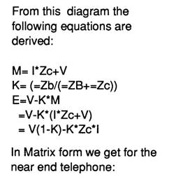
From this diagram the following equations are derived:
M=l*Zc+V
K= (=Zb/(=ZB+=Zc))
E=V-K*M
V=V-K*(l*Zc+V)
=V(1-K)-K*Zc*l
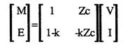
In Matrix form we get for the near end telephone:
If the Telephone is at the far end of the line rearrangement gives:
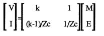
Note: The line current is reversed for ABCD matrix compatibility!
Normally the sending sensitivity Ss is the matched sensitivity so M is twice the line voltage in the models shown above. Different hybrid matrices were used with this factor allowed for.
4 The 2*2 matrix model for Hybrids as found in PABX 2 wire line cards.
For a hybrid, M is replaced by Vin, and E is replaced by a differential amplifier producing Vout, matching impedances on the four wire side are ignored or accommodated in the four wire gains, They do not exist in a digital exchange, as in a digital exchange the voltages are encoded and sent digitally inside the exchange.
There is a model for a four wire exchange with two wire interfaces. This model is simplified by splitting the model into to the three matrices listed below:
a) 2 to 4 wire Hybrid,
b) 4 wire gain/ loss matrix,
c) 4 to 2 wire Hybrid
The model for the four wire exchange model becomes:
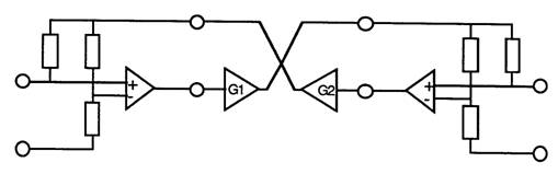
and matrices for each element:
Vout and Vin are the hybrid’s four wire inputs and outputs. The four wire gains matrix connects one hybrid’s Vout to the other hybrid’s Vin. Vout and Vin are intermediate variables and are shown to aid understanding.
These would be multiplied together to form an ABCD matrix.
Note that there is a 6dB loss across the hybrids when driving matched loads. This needs to be allowed for. This again is because of the outputs of G1 and G2 form the EMFs driving the hybrids.
(Note: The AD-BC = 1 reciprocity rule (p262 [8]) does not apply as it does for passive networks so this cannot be used as a rounding error check on the calculations!)
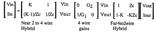
5 Putting a network together
Two telephones and some line make a telephone connection, ignoring the exchange. The circuit below shows the complete network:
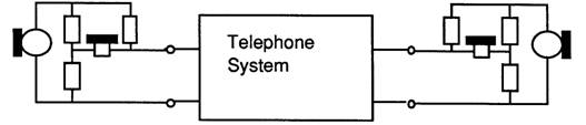
Multiplying the matrices together results in:
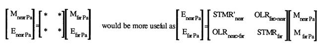
The use of OLR and STMR allude to the Loudness Ratings. These should be OLR' and STMR'. This is an allusion, as OLR and STMR are calculated at 14 frequencies as defined in ITU P.79.
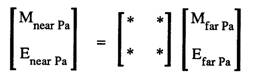
It is evident that the network is in terms of near end microphone and earpiece sound pressures based upon the far end microphone and earpiece sound pressures.
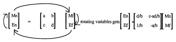
For loudness ratings the acoustics gains (Earpiece pressure/Microphone pressure) are required. By a little rearrangement of variables these can be found.
Below shows that the required function rotates the variables( p264 of [8] expands upon this, but the algebra used to derive the telephone matrix can be used also):
This is useful as it can be used to :
1) Calculated the impedance for zero sidetone for the network,
2) Allows rearrangement of variables to give easy access to the sensitivities.
3) Convert a network into an admittance - parameter network.
4) Application of the function twice allows matrix inversion.
5) Conversion to z parameter matrices.
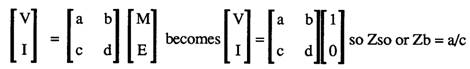
6 Calculating the impedance for zero sidetone
Minimum sidetone is when the earpiece pressure is at a minimum when there is some microphone voltage. So subsituting M=1 and E=0 into the equation below, and then dividing V/l we get the impedance for zero sidetone:
This would be useful with sensitivity analysis software and optimization software to calculate optimum impedences.
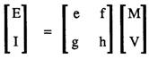
7 Rearrangement for easy access to the sensitivities
For PABX evaluation the SLR, RLR and STMR into a stone bridge and 600 ohm source/load is required. If a series 600 ohm impedance is attached to the near end telephone model then the following sensitivities for the loudness ratings are available as shown below:
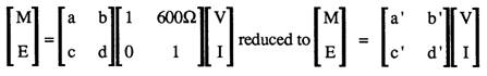
rotated to
8 References:
[8] F.F. Kuo, Network Analysis and Synthesis, Wiley International,1962
[9] N.A Pashtoon,Chap 4 of D.F.EIIiott, Handbook of Digital Signal Processing Engineering Applications,Academic Press, 1987
9 The Turbo Pascal code:-
The Turbo Pascal code for this is:
{----------------------------------------------------------------}

{
//// 6.6 ABCD MATRIX CALCULATION FUNCTIONS
}

{The next set of procedures and functions are
used to evaluate the voltage ratios.
They are collection of two by two matrix manipulation routines - see paper on
calculation of loudness ratings}

FUNCTION multr(rar,rai,rbr,rbi:REAL):REAL;
{returns the real part of a matrix multiplication}
BEGIN
  multr:=rar*rbr-rai*rbi;
END;

FUNCTION multi(rar,rai,rbr,rbi:REAL):REAL;
{returns the imag part of a matrix multiplication}
BEGIN
  multi:=rar*rbi+rai*rbr;
END;


PROCEDURE multmat(nar,nai,nbr,nbi,ncr,nci,ndr,ndi:REAL);
{multiplies the complex two by two matries [r]:=[r]*[n]}
BEGIN
  ar:=rar;ai:=rai;
  br:=rbr;bi:=rbi;
  cr:=rcr;ci:=rci;
  dr:=rdr;di:=rdi;

  rar:=ar*nar-ai*nai+br*ncr-bi*nci;
  rai:=ar*nai+ai*nar+br*nci+bi*ncr;

  rbr:=ar*nbr-ai*nbi+br*ndr-bi*ndi;
  rbi:=ar*nbi+ai*nbr+br*ndi+bi*ndr;

  rcr:=cr*nar-ci*nai+dr*ncr-di*nci;
  rci:=cr*nai+ci*nar+dr*nci+di*ncr;

  rdr:=cr*nbr-ci*nbi+dr*ndr-di*ndi;
  rdi:=cr*nbi+ci*nbr+dr*ndi+di*ndr;

END;  {multmat}

PROCEDURE multabcd(nbr,nbi,ncr,nci:REAL);
{as multmat except n matrix = [1 b] to reduce the number of parameters
                              [c 1]
 intended for simple parrallel of series components }

CONST nar=1;nai=0;
      ndr=1;ndi=0;

BEGIN
  multmat(nar,nai,nbr,nbi,ncr,nci,ndr,ndi);
END;{multabcd}

PROCEDURE multy(yr,yi:REAL);
{multiplies parrallel admmitance}
BEGIN
  multabcd(0,0,yr,yi);
END;

PROCEDURE  multz(zr,zi:REAL);
{multiples series impedance }
BEGIN
  multabcd(zr,zi,0,0);
END;

PROCEDURE inv(VAR xr,xi:REAL);
{ does complex 1/x }
VAR

 d:REAL;

BEGIN
  d:=xr*xr+xi*xi;
  xr:=xr/d;
  xi:=-xi/d;
END;{inv}

{
//// 6.7 4-2 WIRE HYBRID MATRIX CALCULATION FUNCTIONS
}

PROCEDURE calk(VAR yr,yi:REAL; zcr,zci,zbr,zbi:REAL);
{calculates complex zb/(zb+zc) }
VAR
 t,d:REAL;
BEGIN
  inv(zbr,zbi);
  yr:=zcr*zbr-zci*zbi;
  yi:=zcr*zbi+zci*zbr;
  yr:=1+yr;
  inv(yr,yi);
END; {calk}

PROCEDURE twoto4(zcr,zci,zbr,zbi:REAL);
{This models the hybrid inputing 4 wire to 2 wire [ M ] = [   ] [V]
see paper on loudness ratings                     [ E ]   [   ] [I]  }

VAR

ar,ai,br,bi,cr,ci,dr,di:REAL;

BEGIN
  ar:=0.5;ai:=0;
  br:=zcr/2;bi:=zci/2;
  calk(cr,ci,zcr,zci,zbr,zbi);
  dr:=-(cr*zcr-ci*zci);
  di:=-(cr*zci+ci*zcr);
  cr:=1-cr;ci:=-ci;
  multmat(ar,ai,br,bi,cr,ci,dr,di);
END; {twoto4}

PROCEDURE fourto2(zcr,zci,zbr,zbi:REAL);

{This models the hybrid inputing 2 wire to 4 wire [ V ] = [   ] [ M ]
                                                  [ I ]   [   ] [ E ]  }

VAR

ar,ai,br,bi,cr,ci,dr,di:REAL;

BEGIN
  calk(ar,ai,zcr,zci,zbr,zbi);
  inv(zcr,zci);
  br:=1;bi:=0;
  dr:=zcr;di:=zci;
  cr:=((ar-1)*zcr-ai*zci)*2;
  ci:=((ar-1)*zci+ai*zcr)*2;
  ar:=ar*2;ai:=ai*2;
  multmat(ar,ai,br,bi,cr,ci,dr,di);
END; {fourto2}

PROCEDURE convert;
{ This rotates the variables of a two by two matrix clockwise
   [m]=[  ][M]  ==>  [e]=[ ][m]
   [e] [  ][E]       [E] [ ][M] see paper for formulae}

VAR

y11r,y11i,y12r,y12i,y21r,y21i,y22r,y22i,cr,ci:REAL;

BEGIN
  cr:=rbr;ci:=rbi; {calc inverse of b}
  inv(cr,ci);
  {evaluate terms}
  y11r:=rdr;                       y11i:=rdi;
  y12r:=multr(rar,rai,rdr,rdi);    y12i:=multi(rar,rai,rdr,rdi);
  y21r:=1.0;                       y21i:=0.0;
  y22r:=-rar;                      y22i:=-rai;
  {now divide by b and put back}
  rar:=multr(y11r,y11i,cr,ci);      rai:=multi(y11r,y11i,cr,ci);
  rbr:=rcr-multr(y12r,y12i,cr,ci);  rbi:=rci-multi(y12r,y12i,cr,ci);
  rcr:=multr(y21r,y21i,cr,ci);      rci:=multi(y21r,y21i,cr,ci);
  rdr:=multr(y22r,y22i,cr,ci);      rdi:=multi(y22r,y22i,cr,ci);
END; {convert}

PROCEDURE fwgains(lfr,lfi,gnr,gni:REAL);
{This procedure applies the gains for four wires circuits
   [ 0      lf>n]
   [ gn>f   0   ] }

VAR

ar,ai,br,bi:REAL;

BEGIN
  multmat(0.0,0.0,lfr,lfi,gnr,gni,0.0,0.0);
END; {fwgains}

{
//// 6.8 ARTIFICIAL LINES MATRIX CALCULATION FUNCTIONS
}
PROCEDURE lines (length : REAL);
{ This procedure evaluates line sections for unloaded line.
  The model is that of BTR 1050
  Operation is akin to long multipliction , 100 meter sections
  are conditionally added}

VAR

                     len,il,il2 : INTEGER;
aar,aai,abr,abi,acr,aci,aqr,aqi : REAL;


BEGIN
  len:=ROUND(length*10);{length is km of line}
  IF len <> 0 THEN
  BEGIN
    il:=0;
    il2:=1;
    aar:=rar;   aai:=rai;
    abr:=rbr;   abi:=rbi;
    acr:=rcr;   aci:=rci;
    aqr:=rdr;   aqi:=rdi;
    rar:=1;      rai:=0;
    rbr:=0;      rbi:=0;
    rcr:=0;      rci:=0;
    rdr:=1;      rdi:=0;

   {100 metre section = O---[===]----O
                          I       I
                         ===     ===  2.5nF
                          I       I
                        O---[===]----O
                             16.8 ohm         }

    multy(0,w*2.5E-9);
    multz(16.8,0);
    multy(0,w*2.5E-9);
    WHILE len > 0 DO
    BEGIN
      IF (len-2*(len DIV 2))=1 THEN
      BEGIN
        ar:=aar;  ai:=aai;
        br:=abr;  bi:=abi;
        cr:=acr;  ci:=aci;
        dr:=aqr;  di:=aqi;

        aar:=ar*rar-ai*rai+br*rcr-bi*rci;
        aai:=ar*rai+ai*rar+br*rci+bi*rcr;

        abr:=ar*rbr-ai*rbi+br*rdr-bi*rdi;
        abi:=ar*rbi+ai*rbr+br*rdi+bi*rdr;

        acr:=cr*rar-ci*rai+dr*rcr-di*rci;
        aci:=cr*rai+ci*rar+dr*rci+di*rcr;

        aqr:=cr*rbr-ci*rbi+dr*rdr-di*rdi;
        aqi:=cr*rbi+ci*rbr+dr*rdi+di*rdr;

        il:=il+il2
      END;
      multmat (rar,rai,rbr,rbi,rcr,rci,rdr,rdi);
      il2:=il2+il2;
      len:=len DIV 2
    END;
    rar:=aar;   rai:=aai;
    rbr:=abr;   rbi:=abi;
    rcr:=acr;   rci:=aci;
    rdr:=aqr;   rdi:=aqi;
  END
END; {line}

{
//// 6.9 COMPLETE CONNECTION CALCULATION FUNCTIONS
}
PROCEDURE throughcalc (length1,length2 : REAL);
{throughcalc exercises a connection for different length lines
It calcultes the voltage ratios for the three connection types supported,
then uses these to calculate the loudness ratings }

VAR

c : freq_index_T;
k1,k2,k3,zlr,zli:REAL;

BEGIN
  olr:=0;
  olr1:=0;
  rlr:=0;
  slr:=0;
  stmr:=0;
  stmr2:=0;
  k:=1;
  FOR c:= MIN_FREQ_INDEX TO MAX_FREQ_INDEX DO
  BEGIN
    w:=freq[c]*2*pi;
    rar:=1.0;rai:=0.0;
    rbr:=0.0;rbi:=0.0;
    rcr:=0.0;rci:=0.0;
    rdr:=1.0;rdi:=0.0;

    twoto4(phonestore[near,c,zcr],phonestore[near,c,zci],
      phonestore[near,c,zbr],phonestore[near,c,zbi]);  {near phone hybrid}
    lines(length1);                                     { line  }
    fourto2(work[c,EP_zcnr],work[c,EP_zcni],work[c,EP_zbnr],work[c,EP_zbni]);   {exchange hybrid}
    fwgains(work[c,EP_gnfr],work[c,EP_gnfi],work[c,EP_gfnr],work[c,EP_gfni]); {gains}
    twoto4(work[c,EP_zcfr],work[c,EP_zcfi],work[c,EP_zbfr],work[c,EP_zbfi]);    {exchange hybrid}
    lines(length2);                                     {line   }
    { choice of phone   to phone
                       to  to 600 ohm
                           to stonebridge and 600ohm}
    IF ct = 'p' THEN
    BEGIN {phone to phone option }
      fourto2(phonestore[far,c,zcr],phonestore[far,c,zci],
         phonestore[far,c,zbr],phonestore[far,c,zbi]);{far phone hybrid}
      convert;{convert from 'ABCD' format to 'E =[r] M' format [r]= [a b ]
                                                                    [c d ] }

      (* olr k's= calculated loss in volts *)
      k:=rbr*rbr+rbi*rbi;                             {b= EN/MF}
      m:=0.0175*(10.0*LN(k)/ln10-wo[c]+phonestore[far,c,ss]
         +phonestore[near,c,sr]);
      olr1:=olr1+exp(m*ln10);
      k:=rcr*rcr+rci*rci;                             {c= EF/MN}
      m:=0.0175*(10.0*LN(k)/ln10-wo[c]+phonestore[near,c,ss]
         +phonestore[far,c,sr]);
      olr:=olr+exp(m*ln10);

      (*stmr k's= calculated loss in volts *)

      k:=rar*rar+rai*rai;                             {a= EN/MN}
      m:=0.0225*(10.0*LN(k)/ln10-wm[c]+phonestore[near,c,ss]
         +phonestore[near,c,sr]);
      stmr:=stmr+exp(m*ln10);
      k:=rdr*rdr+rdi*rdi;                             {d= EF/MF}
      m:=0.0225*(10.0*LN(k)/ln10-wm[c]+phonestore[far,c,ss]
         +phonestore[far,c,sr]);
      stmr2:=stmr2+exp(m*ln10);
    END
    ELSE
    BEGIN           {phone to trunk option }
      IF ct='t' THEN
      BEGIN { a stone bridge is inserted ( see BS 6317 ammendments)}
        zlr:=400;zli:=w*3;{inductors are total of 400 ohm + 3 H}
        inv(zlr,zli);
        multy(zlr,zli);     {stone bridge inductors};
        multz(0,-1/(w*1.0E-6));{ the capacitors(1uF)};     {M = [  ]V}
        multy(zlr,zli);
      END;
      multy(+1/600,0);      {Interface };          {E = [  ]I}
      k1:=rar*rar+rai*rai;     {a=M/V}
      k:=0.0175*(-10.0*ln(k1)/ln10-ws[c]+phonestore[near,c,ss]);
      slr:=slr+exp(k*ln10);
      multy(-1/600,0);      {take off 600 ohm load and add 600 ohm V generator}
      multz(600,0);
      convert;              {convert to this format E=[  ]M}
      k2:=rbr*rbr+rbi*rbi;  {b=E/V}   {       I=[  ]V}
      k:=0.0175*(10.0*ln(k2*4)/ln10-wr[c]+phonestore[near,c,sr]);
      {k2=E*E/V*V want e/(v/2)}
      rlr:=rlr+exp(k*ln10);
      k1:=rar*rar+rai*rai;    {a=E/M }
      k:=0.0225*(10.0*ln(k1)/ln10-wm[c]+phonestore[near,c,ss]
          +phonestore[near,c,sr]);
      stmr:=stmr+exp(k*ln10);
    END;
  END;
  resultscreen(length1,length2)
END;{throughcalc}

PROCEDURE loopcontrol;
{ This execises the connection for different length lines }
VAR

   l1,l2,cc : INTEGER;
      length:real;
      escape:boolean;

BEGIN
  escape := FALSE;
  with linlen[1] do
  BEGIN {with}
    length:=from;
    while (length < too ) and not escape do
    BEGIN
      throughcalc(fixed,length);
      length:=length + step;
      escape := check_escape;
    END;
  END;  {with}
  with linlen[2] do
  BEGIN {with}
    length:=from;
    while ( length < too ) and not escape do
    BEGIN
      throughcalc(length,fixed);
      length:=length + step;
      escape := check_escape;
    END;
  END;  {with}
  with linlen[3] do
  BEGIN  {with}
    length:=from;
    while ( length < too ) and not escape do
    BEGIN
      throughcalc(length,length);
      length:=length + step;
      escape := check_escape;

    END;
  END;   {with}
END;{loopcontrol}