Update:- 12/04/2023
Consider a terminal connected to the Network at the Network Termination Point , NTP.

[terminal]---+---[ line ]---[exchange]
            NTP

What is the Zc of the Terminal?
What is the Zc of the Exchange?
What is the Z looking into the line towards the Exchange at the NTP?
What is the Z looking into the line towards the Terminal at the Exchange?

The NTP is nominally 2km from the Exchange.
Artificial Line
What is the impedance looking into the Artificial line?
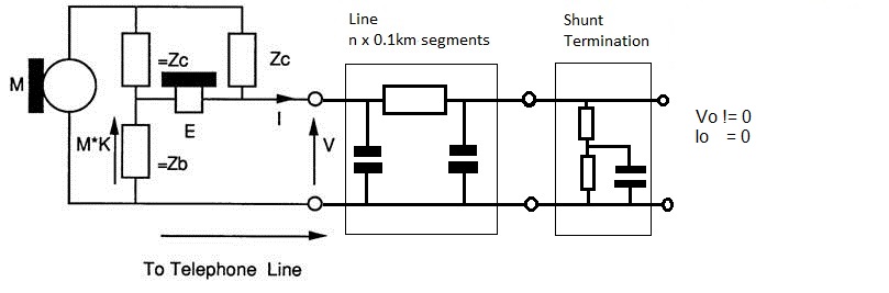
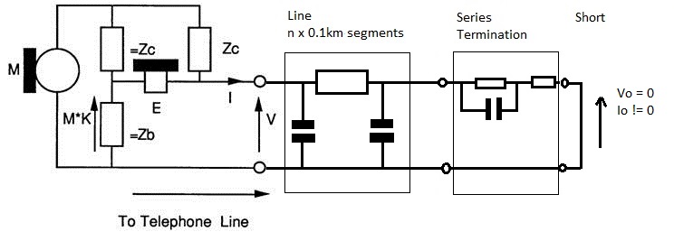
2x2 matrix model being simulated:-
[V] = [ Line(length) ] [ nominal exchange input impedance is 370 ohm + 620 ohm || 310 nF ] [v]
[I] [i]
Use Shunt Termination when you need Io =0 and Vo != 0
Use Series Termination when you need Vo =0 and Io != 0
Complex Z add exchange Z = 370+ 620//310nf [ :
//The terminal Figure 1: Terminal Complex Impedance Network = 370+ 620//310nf
//The nominal exchange input impedance is 300 ohm + 1000 ohm || 220 nF (see Figure 2).
//The Balance Impedance, Zso is 270R +1500R || 180nf
//See Zso Fig6 , p267 British Telecommunications Engineering. Vol 5 Jan 1987
we need to plot what we present. we want V/I
Magintude, against Frequency Hz :
Complex Z:
NOTE: The Graph "sub-samples" or "aliases" if the delay is greater than 10ms as the graph is plotted against freq, incrementing by 50Hz. 1/50Hz is 20ms , so the frequency should really be incremented with a fine step, the more delay.
The delays introduced by digital time switches and packetization are a problem and
this simulation suffers from "sub-sampling and aliasing". This makes the graphs more artistic!
/*
  for ( var fr = 100 ; fr < 4000; fr +=50 ) {
    c=1
    // jitter the frequency used to show up aliasing.
    freq[c] = fr+Math.random(1)*2.0-1.0
*/
Calculation [ A B C D ]:
/*
[Vo] = [ a b ][Io]
[Vi]   [ c d ][Ii]
Io = 0 as Shunt Zterm Added

a = Do not use, as Io = 0
b = Vo/Ii   is this useable, but is Voutput/Iinput
c = Do not use, as Io = 0
d = Zin
*/
b = Vo/Ii is this useable
d = Zin
Vo/Vi - "gain" across line.
dB mag |Vo/Vi| - "gain" across line.
k = Zline/(Zc+Zline) // ideal should be 0.5+j0
k = Zline/(Zc+Zline)
dB mag| Zline/(Zc+Zline)| // ideal should be -6dB
Overview - Also see source code
--[line]--[term]--
V near Voltage,I near Current
v far voltage, i far current
NOTE: Iin, i flows into the two port Two Port network, Iout or I flows out. This enables the line to be chained together.
[V] = [ ][v]
[I] [i]
use convert to rotate vars to
[I] = [ ][V]
[i] [v]
[i] = [ ][I]
[v] [V]
[v] = [ ][i]
[V] [I]
/* calculate Zo
Zi = aZi+b / (cZi+d)
zi*(cZi+d) = aZi+b
zi*zi*c+(d-a)*zi-b= 0
zo = sqrt( zopen * zshort )
[Vi] = [ a b ][Vo]
[Ii] [ c d ][Io]
// open Io = 0
[Vi] = [ a b ][Vo] = [ a 0 ]
[Ii] [ c d ][Io] [ c 0 ]
Zi = a/c
// closed Vo = 0
[Vi] = [ a b ][Vo] = [ 0 b ]
[Ii] [ c d ][Io] [ 0 d ]
Zi = b/d
Zo = sqrt( a/c * b/d ) = ( a * b * inv(c) * inv(d) )
http://www.ping.be/~ping1339/complget.htm#Square-roots-and-com
*/