Consider a terminal connected to the Network at the Network Termination Point , NTP.

[terminal]---+---[ line ]---[exchange]
            NTP

What is the Zc of the Terminal?
What is the Zc of the Exchange?
What is the Z looking into the line towards the Exchange at the NTP?
What is the Z looking into the line towards the Terminal at the Exchange?

The NTP is nominally 2km from the Exchange.
This page calculates z presented to a phone by a line, exhange, line and termination. Use it to explore how delay and far end trans hybrid loss modify the presented Z.
The theory for this was formulated in a pre digital age. The end to end delay was minimal.
The delays introduced by digital time switches and packetization are a problem and this simulation suffers from "sub-sampling and aliasing". This makes the graphs more artistic!
The typical local phone call, What is Zin presented to the phone?
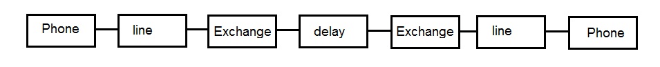
Model Zin presented by Phone line, hybrid, loss, hybrid, line, phone

 2 wire, line, 2 to 4 wire, time-switch delay, 4 wire to 2 wire, line , termination.

--line--{==Loss==}--line--termination

Pre digital exchanges used a 3dB Loss. The far end tran- hybrid loss was not audible, so was increased to 6dB.

Analogue exchanges had complicated loss plans as the transmission loss was dependent of length of the transmission.

Digital exchanges converted the voice to samples, and the sample's values did not suffer loss end to end.

VoIP has much greater delays 40ms, 80ms, and some expensive smart phones have delays of 460ms.

//The terminal Figure 1: Terminal Complex Impedance Network = 370+ 620//310nf
    var z_complex_z = z_abc(370, 620, 310.0e-9 , freq[c] );

//The nominal exchange input impedance is 300 Ù + 1000 Ù || 220 nF (see Figure 2).
    var z_complex_znom = z_abc(300.0, 1000.0, 220.0e-9 , freq[c] );


Summary:=
// 1,z_complex_z)    Terminal Complex Impedance Network = 370+ 620//310nf
// 2,z_complex_znom) The nominal exchange input impedance is 300 ohm + 1000 ohm || 220 nF
// Balance Z not explictlty stated.

Connection being modelled:-

lines( ll );

// exchange Hybrid
fourto2(z_complex_znom.r,z_complex_znom.i , z_complex_z.r,z_complex_z.i )

// Digital loss and delay
fwgains(rs.nflossr,rs.nflossi,rs.fnlossr,rs.fnlossi);

// exchange Hybrid
twoto4(z_complex_znom.r,z_complex_znom.i , z_complex_z.r,z_complex_z.i );

lines( ll );

termination

convert();
convert();
convert();

Vin = A B Vout
Iin   C D Iout

becomes

Vout = A B Iout
Vin    C D Iin

so Zin is D

You decide what A,B,C are, considering that the  input was open circuit and the output was terminated.

Use a timer to sweep a variable.

The telephone line is modelled using 100 m sections. It uses a modified "Successive Approximation".

    100 metre section = O---[===]----O
                          I       I
                         ===     ===  2.5nF
                          I       I
                        O---[===]----O
                             16.8 ohm
Magintude in dB, against Frequency Hz :
I want to plot Zin

Vin = A B Vout
Iin   C D Iout

Build up Connection
  --[ line ]-- [hybrid]==[hybrid]--[termination]--

By adding the termination, Iout is zero as the termination has been added.

convert() three times to get

Vout = A B Iout
Vin    C D Iin

So D is the input Z. Plot this to see far end reflection affecting Zin.
NOTE: The Graph "sub-samples" or "aliases" if the delay is greater than 10ms as the graph is plotted against freq, incrementing by 50Hz. 1/50Hz is 20ms , so the frequency should really be incremented with a fine step, the more delay.
The delays introduced by digital time switches and packetization are a problem and this simulation suffers from "sub-sampling and aliasing". This makes the graphs more artistic!
/*
  for ( var fr = 100 ; fr < 4000; fr +=50 ) {
    c=1
    // jitter the frequency used to show up aliasing.
    freq[c] = fr+Math.random(1)*2.0-1.0
*/
all: A: B: C: D: Edit the source code to enter the phone and exchange data.
This page calculates the End to End gains and sidetone gains.
The early theory for this page was forulated in a pre digital age.
The delays introduced by digital time switches and packetization are a problem.
However, it was a rule of thumb that transmission line effects needed to be considered when the lengths were greater than an 1/8th of a wavelength. It may be better to rephrase this in terms of delay and period. If the delay is greater than an 1/8 of a period, transmission line theory must be considered.
For an 8kHz sample rate, the period between samples is 125us. 1kHz has a period of 1ms.
A time switch used in digital exchanges needs at least 125us, and is more than likely a few multiples.
Delays of tens of ms are now typical. VoIP may have a 20ms buffer!
So we are well into the rule requiring us to consider transmission line effects and reflections must be minimised to prevent problems.
The Wave equation relates distance, frequency and speed.
http://www.bbc.co.uk/bitesize/intermediate2/physics/waves_and_optics/wave_equation/revision/1/
The Wave Equation

The wave equation is a very important equation that is often used to help us describe waves in more detail.

Wave Speed = Frequency x Wavelength

v = f x lambda

Where:

Wave speed is in metres per seconds (m/s or ms-1)

Frequency is in Hertz (Hz).

Wavelength is in metres (m).

NB:

It should be noted that some particular waves have their own specific speeds.
The speed of light and all of the EM spectrum is 300,000,000 m/s or 3x10^8 m/s.

The speed of sound in air is 340 m/s.

The speed of light and sound in materials will alter, please check very carefully at the front of the paper in the data sheet which speed to use.

The speed of VoIP signal. is dimension of phone divided by the buffer size. Say phone is ~10cm wide , delay 20ms, "velocity" = 0.01/0.020 = 1/2 m/s
added Line A-leg , B-leg