References: Paul Robson's page | copy of Paul Robson's pages | Karen Orton's Page techlib.com/area_50/Readers/Karen/micro.htm | more.. | MK_14 Rom listing | My notes | Scmp_Code | Scmp info | Elector Scmp info | ins grid | ins grid | sc/mp datasheet | my web site |
 _  _   _            _  _     _
|_||_  |  | |   _|| |_ |_||  |_||_|
| | _| |_ | |  |_||  _||  |_ | | _|
|
For Tablets:
timed press ---___---.
|
Use the left mouse to press
the buttons below:-
|
example1: XOR and store press abort 0 F 2 1 Mem C 4 Mem A A Mem E 4 Mem 5 5 Mem C 8 Mem 0 2 Mem 3 F ;now to execute abort 0 F 2 2 GO ;you should read: 0F29 FF |
SCIOS saves after 3F, 0FF9 p1h 0FFA p1l 0FFB p2h 0FFC p2l 0FFD Acc 0FFE Extension 0FFF Status The status register:- 7 6 5 4 3 2 1 0 cy/l,OV,SB,SA,IE,F2,F1,F0 Bit Function Notes 0 F0 Output Line 1 F1 Output Line 2 F2 Output Line 3 IE Interrupt Enable 4 SA Input Line + INT, 5 SB Input Line 6 OV Overflow 7 CY/L Carry / Link bit |
abort 0F22 Term

or
abort 0F21 Mem
C4 Mem
AA Mem
E4 Mem
55 Mem
C8 Mem
02 Mem
3F
;now go and execute
abort 0F22
G
;
you should read:
0F29 FF

The code assembled using rcasm or asm:
   32 0f22:
   33 0f22:             	; load accumulator with 0xAA eor with 0x55 and store
   34 0f22: c4 aa       	ldi	0aah
   35 0f24: e4 55       	xri	055h
   36 0f26:
   37 0f26: c8 02       	st	2 (0)
   38 0f28:             	; return to the monitor
   39 0f28: 3f          	xppc	3
   40 0f29:
   41 0f29:
   42 0f29:             	; next code is overwritten by result.
   31 0f20: 90 00       	jmp	main0
   32 0f22:
   33 0f22:             main0:
   34 0f22:             	; reload display pointer.
   35 0f22: c4 00       	LDI	Disp.0
   36 0f24: 31          	XPAL	1
   37 0f25: c4 0d       	LDI	Disp.1
   38 0f27: 35          	XPAH	1
   39 0f28:
   40 0f28: c4 aa       	ldi	0aah
   41 0f2a: cd 00       	st	@0(1)
   42 0f2c:
   43 0f2c: 90 f4       	jmp	main0
   44 0f2e:
   45 0f2e:
m is the mode bit. If 1 the instruction is auto-indexed, if 0 it is indexed. pp refers to a pointer register, P0..P3
If mpp is 100 (you can't auto index on the program counter), this is immediate mode. The data is in the next byte ( ). There is, of course, no store immediate.
Double Byte Instructions
| LD/LDI | 11000mpp dddddddd | 18/10 | AC := (EA) |
| ST | 11001mpp dddddddd | 18/10 | (EA) := ACOR |
| AND/ANI | 11010mpp dddddddd | 18/10 | AC := AC & (EA) |
| OR/ORI | 11011mpp dddddddd | 18/10 | AC := AC | (EA) |
| XOR/XRI | 11100mpp dddddddd | 18/10 | AC := AC ^ (EA) |
| DAD/DAI (1) | 11101mpp dddddddd | 23/15 | AC,CYL := AC+(EA)+CY/L, base 10 |
| ADD/ADI | 11110mpp dddddddd | 19/11 | AC,CYL := AC+(EA)+CY/L |
| CAD/CAI (2) | 11111mpp dddddddd | 20/12 | AC,CYL := AC+~(EA)+CY/L |
| ILD | 101010pp dddddddd | 22 | AC,(EA) := (EA)+1 |
| DLD | 101110pp dddddddd | 22 | AC,(EA) := (EA)-1 |
| JMP | 100100pp dddddddd | 9 | PC := EA |
| JP | 100101pp dddddddd | 9/11 | if AC > 0 PC := EA |
| JZ | 100110pp dddddddd | 9/11 | if AC = 0 PC := EA |
| JNZ | 100111pp dddddddd | 9/11 | if AC <> 0 PC := EA |
| DLY | 10001111 dddddddd | (3) | Delay |
(1) DAD and DAI are decimal add instructions. These do not affect the overflow
(2) CAD and CAI are complement and add instructions, these are used to subtract.
(3) Delays for 13 + 2 * AC + 2 * dddddddd + 2^9 * dddddddd cycles. (13-131,593), AC is set to -1 afterwards.
Single Byte Instructions
| lde | 01000000 | 6 | AC := E |
| xae | 00000001 | 7 | AC <-> E |
| ane | 01010000 | 6 | AC := AC & E |
| ore | 01011000 | 6 | AC := AC | E |
| xre | 01100000 | 6 | AC := AC ^ E |
| dae | 01101000 | 11 | AC := AC + E + CY/L base 10 |
| ade | 01101000 | 7 | AC := AC + E + CY/L |
| cae | 01111000 | 8 | AC := AC + ~E + CY/L |
| xpal | 001100pp | 8 | AC <-> P.Low |
| xpah | 001101pp | 8 | AC <-> P.High |
| xppc | 011111pp | 7 | P <-> P0 |
| sio | 00011001 | 5 | Sout := E0,E := E >> 1, E7 := Sin |
| sr | 00011100 | 5 | AC := AC >> 1 |
| srl | 00011101 | 5 | AC := AC >> 1,AC7 := CY/L |
| rr | 00011110 | 5 | rotate right AC |
| rrl | 00011111 | 5 | rotate right AC,CY/L |
| halt | 00000000 | 8 | Pulse 'H' (doesn't stop the CPU) |
| ccl | 00000010 | 5 | CY/L := 0 |
| scl | 00000011 | 5 | CY/L := 1 |
| dint | 00000100 | 6 | IEN := 0 |
| ien | 00000101 | 6 | IEN := 1 |
| csa | 00000110 | 5 | AC := S |
| cas | 00000111 | 6 | S := AC (not SA or SB) |
| nop | 00001000 | 5 | no operation |
Assembler notes
Double byte instructions are represented as follows :-
| Immediate | ldi 4Ch | (immediate mode) |
| Indexed | ld 41(0) | EAC := 42 + P0 |
| Auto Indexed | ld @4(1) | EAC := P1 then P1 := P1 + 4 |
| Direct | ld 42h | EAC := 42 (see below) |
There is no actual 'direct' mode. It is converted by the assembler into a PC-relative instruction.
Because of the pre-increment fetch problem, TASM in its normal form will assemble data references one out. So if you are going to use a data area, do it as follows :-
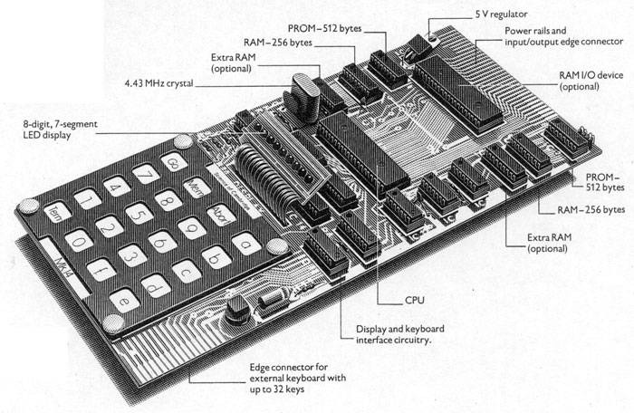
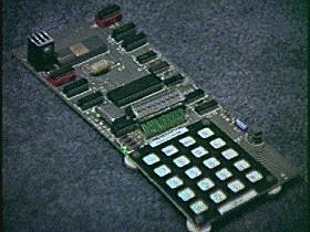
The MK14 had ram, rom, a National SC/MP cpu, display, keyboard, glue logic, and power supply This simulation has an array called Memory[], and the cpu is simulated. The display and keyboard have to be emulated, so that the code the SC/MP cpu runs works. One of the nice things was the SC/MP had "microcontroller" features with the three outputs and two inputs to the chip. It would be nice to have cheats as well. Poke bytes into memory. Offset calculators. LEDs on port pins. Switches on SIO input.
The display is at 0x0900+x where x is the digit. It is also at 0xd00+x. The MK14 had a 4 bit latch and binary decoder 74LS154 mux. The display lit one digit at a time. To illumiate the LED segments, the bit pattern is written into the address, and latch. The MK14 keeps displaying until the next write to the display. (* This simulation does not do this yet! *) Update display() when CPU writes to the display memory. This clobbers the speed, so only update webpage display every 150ms tick. This program uses SVG graphics and innerHTML to render the 7-segment display. It reads Memory[ 0x900 ] to Memory[ 0x909 ] at the moment.
Buttons:-

reset

GO	MEM	Abort	A
7	8	9	B
4	5	6	C
1	2	3	D
term 	0	F	E

Layout:-
-----------------------------------
bit	|	7	6	5	4	3	2	1	0
-----------------------------------
ra3	|	7	6	5	4	3	2	1	0
ra2	|							9	8
ra1	|	Te			Ab 	Me	Go
ra0	|	F	E			D	C	B	A

http://www.javascript-coder.com/button/javascript-button-p1.phtml
This ports Paul Robson's C code.

It needs the registers:
	ACC
	E
	status
	p0,p1,p2,p3

Functions:
	reset
	instructionInterpreter -  See Paul Robinson - I used his code.
	helper functions
Only the first 12 bits of the program counter are decoded

000-1FF  512 byte SCIOS ROM  Decoded by 0xxx
200-3FF  ROM Shadow / Expansion RAM
400-5FF  ROM Shadow / Expansion RAM
600-7FF  ROM Shadow / Expansion RAM
800-87F  128 bytes I/O chip RAM  Decoded by 1xx0
880-8FF  I/O Ports  Decoded by 1xx0
900-9FF  Keyboard & Display  Decoded by 1x01
A00-AFF  I/O Port & RAM Shadow
B00-BFF  256 bytes RAM (Extended) / VDU RAM  Decoded by 1011
C00-CFF  I/O Port & RAM Shadow
D00-DFF  Keyboard & Display Shadow
E00-EFF  I/O Port & RAM Shadow
F00-FFF  256 bytes RAM (Standard) / VDU RAM  Decoded by 1111
References to other pages provide enough information. It also allows me to provide a sandpit for playing with machine code
/********************************************************************/
/*																	*/
/*		Portable MK14 emulator in 'C' by Paul Robson	1998		*/
/*																	*/
/*        ported to JavaScript by Doug Rice , June 2016, March2017  */
/*																	*/
/*				I built a kit in 1977 or 78								*/
/*																	*/
/*								CPU Emulator						*/
/*																	*/
/********************************************************************/