This experimental page started off experimenting with the CANVAS for drawing and audio.
Audacity can record signals from a phone line with a suitable circuit and cheap sound card.
This page can audio decode samples exported from Audacity to the text sent using the V.21 modem.
It is easy to make mistakes, so this can be tweeked to suit.
This page uses IIR Goetzel resonators / filters to look for the modem's FSK tones that encode the 1's and 0's.
These are decoded by a 300 baud UART to decode text that Audactity cannot decode.
The red lines are the IIR output, the blue lines are debug.
It is still being tested. Looking for 0x41 , STOP , start , 1,0,0,0, 0,0,1,0, 1
x:
|
|
x scale:
|
Y scale: |
presets:
|
|
|
IIR Goetzel resonators tuned to:-
mark:[1,red]: Hz and
space:[0,orange]: Hz,
resonance - mag: mag must be less than 1 iir smoothing
#define NBQ 2
REAL biquada[]={0.9802510163831233,-1.4029516825028896,0.979859571303725,-1.374238052846466};
REAL biquadb[]={0.9999999999999998,-1.4027228552933624,0.9999999999999998,-1.4027228552933624};
REAL gain=1.0203506341124682;
NBQ
REAL biquada[]={
REAL biquadb[]{
GAIN
UART:baudot
baud: 50,110,300,75,600,1200
V.21 2)The nominal characteristic frequencies;
channel No. 1 (FA = 1180 Hz and Fz = 980 Hz);
channel No. 2 (FA = 1850 Hz and Fz= 1650 Hz).
BAUDOT 1400,1800
BELL103 - The MARK and SPACE seem to be inverted.
https://www.dsprelated.com/showthread/comp.dsp/65894-1.php v.21 bell103 mark space
Decoded:
found
found
Samples captured using Audacity. mono, 8000 samples per second.
Generate samples tools
This section generates samples to decode to keep the web page smaller.
extra stopBits:
random extra number of stop bits between characters: bits
Send:
BAUDOT: use UPPERCASE and l for letters and f for FIGS/numbers. Start with "lfl "
These modems use AFSK modulation at 300 baud and 300 bps, at the following
frequencies (in Hertz):

Bell 103
  Originate
    1170 = Carrier
    1070 = Space (Carrier - 100Hz)
    1270 = Mark (Carrier + 100Hz)
  Answer
    2125 = Carrier
    2025 = Space (Carrier - 100Hz)
    2225 = Mark (Carrier + 100Hz)

ITU-T v.21
  Originate
    1080 = Carrier
    1180 = Space (Carrier + 100Hz)
    980 = Mark (Carrier - 100Hz)
  Answer
    1750 = Carrier
    1850 = Space (Carrier + 100Hz)
    1650 = Mark (Carrier - 100Hz)


 START - SPACE - "0" - RS232 or V.28 more than 3V  - Microcontroller TX low
 STOP  - MARK  - "1" - RS232 or V.28 less than -3V - Microcontroller TX High

 Note: The MAX232 chips invert the voltages. Microcontrollers TX and RX are not.

 Serial:-
 -----_____x====x====x====x====x====x====x====x====x----x-------------------------
      START  0    1    2    3    4    5    6    7   stop   til next start bit.

 Drawn using wavedrom:-


  BAUDOT: - 5 bit
* carrier (for 150ms) + 0 + 11000 + 1 (for 40ms)
*
* 0 - 1800Hz - SPACE
* 1 - 1400Hz - MARK
* START 0
* STOP  1
*

   ITU V.23
2 Modulation rates and characteristic frequencies for the forward data-transmission channel
						F0         FZ       FA
		                         symbol 1, symbol 0,
                            	  mark   space
Mode 1: up to  600 bauds 1500 Hz 1300 Hz 1700 Hz
Mode 2: up to 1200 bauds 1700 Hz 1300 Hz 2100 Hz


4 Modulation rate and characteristic frequencies for the backward channel

The modulation rate and characteristic frequencies for the backward channel are as follows:

                                FZ     FA
                               mark   space
Modulation rate up to 75 bauds 390 Hz 450 Hz

In the absence of any signal on the backward channel interface, the condition Z signal is to be transmitted
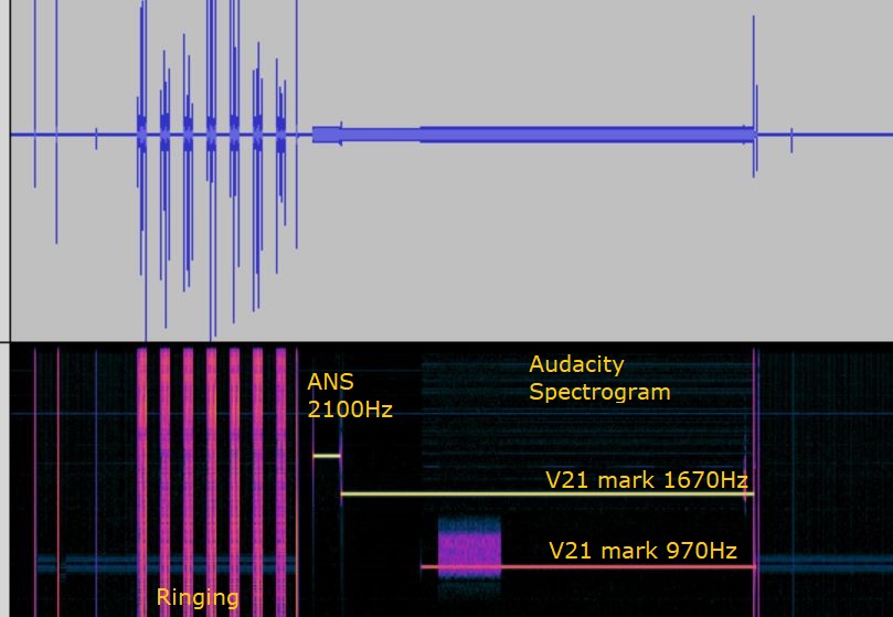
Using Audacity to investigate a modem
Audacity was used to record the modem signals on the phone line.
Audacity's spectrum and spectrogram can indicate what to look for. But it cannot decode DTMF or text carried by V.21 modems. It can export the samples and these can in pasted into this web page
The picture below shows an incoming call to a modem. You can see the ringing, the 2100Hz ANS tone and the V.21(h) carrier, the V.21(l) carrier and a burst of text. It is also possible to measure the bit rate.
However it cannot decode V.21. So you can use this web page to decode the burst of text, and I have added a notch filter to remove the V.21(h) carrier.
A modem using the ITU V.8 spec, has other intersting bursts of characters to decode. Other pages can decode DTMF and BAUDOT captured using Audacity.
It is quite simple to analyse the samples exported from Audacity using JavaScript.
The samples are passed into IIR filters to detect the V.21 FSK signals. Logic is used to find the "1"'s and "0"'s. These are fed into the UART.
Countdown State machines are used for the FSK logic, UART and DEBUG.
The UART emits characters. Parity may need to be stripped, and the decoded text can be displayed.
Some Design Notes, used when thinking about how to write this web page
input --- filters --- comparator --- UART
8000 samples per seconds
300 baud = 26.667
UARTS normally use a x16 clock
300 x 16 is 4800Hz clock
START - SPACE "0" - V.28 more than 3V - PIC TX low - PIC RX low -
STOP - MARK "1" - V.28 less than -3V - PIC TX High - PIC TX High -
UART - for each time slice increment t
START,bit0,1,2,3,4,5,6,7,STOP
use a count down state machine, decrement each sample. 8000 samples per second.
0 - stop
1
START - SPACE - "0" - RS232 or V.28 more than 3V - Microcontroller TX low
STOP - MARK - "1" - RS232 or V.28 less than -3V - Microcontroller TX High
Note: The MAX232 chips invert the voltages. Microcontrollers TX and RX are not.
Serial:-
-----_____x====x====x====x====x====x====x====x====x----x-------------------------
START 0 1 2 3 4 5 6 7 stop til next start bit.
Drawn using wavedrom:-
The filter function uses an iir filter.
The energy is measured using the delayed output squared.
// take 4 samples - want the relative energy between the MARK frequency and SPACE frequency.
opA[ i ] =
z[0]*z[0]
+z[1]*z[1]
+z[2]*z[2]
+z[3]*z[3]
/*
*
* iir filter.
*
*
--X---[ z-1 ]----[z-1]-----
| | |
| k -1
| | |
\------------------------
*
*
from wikipedia:-
Nterms defined here
Kterm selected here
ω = 2 * π * Kterm / Nterms;
cr = cos(ω);
ci = sin(ω);
coeff = 2 * cr;
sprev = 0;
sprev2 = 0;
for each index n in range 0 to Nterms-1
s = x[n] + coeff * sprev - sprev2;
sprev2 = sprev;
sprev = s;
end
power = sprev2*sprev2 + sprev*sprev - coeff*sprev*sprev2 ;
*
*/
/*
* https://sites.google.com/site/hobbydebraj/goertzel-algorithm-dtmf-detection
*/
var z1= "0,0,0,0".split(",")
var z2= "0,0,0,0".split(",")
// IIR Goetzel resonators tuned to:-
// Poles on the unit circle oscillate at f/FS where FS is sample rate.
// for resonators, to detect frequency.
// bring the polls in from the unit circle, using mag, which must be less than 1.0 for stability.
var mag = 0.9
//
// Z = exp( j2PI F/FS )
//
// 1/(zero on the unit circle.
// 1/(1 - mag*exp( j2pi f/Fs ) )(1 - mag*exp( -j2pi f/Fs ) )
// 2cos(x) = exp(jx)+exp(-jx) where x=2Pi F/FS
//
k1= "0.0, 0.0, 0.0".split(",")
k1[0] = mag*2.0*Math.cos( 2.0*Math.PI*( freq_l *1.0/8000.0) )
k1[1] = -mag*mag
k2= "0.0, 0.0, 0.0".split(",")
k2[0] = mag*2.0*Math.cos( 2.0*Math.PI*( freq_h *1.0/8000.0) )
k2[1] = -mag*mag
function iir2_ts( i, ip,z, k, opA ){
z[3]=z[2]*1.0
z[2]=z[1]*1.0
z[1]=z[0]*1.0
z[0]= ip*1 +k[0]*z[1] +k[1]*z[2]
// take 4 samples
opA[ i ] =
z[0]*z[0]
+z[1]*z[1]
+z[2]*z[2]
+z[3]*z[3]
}
NOTE: DSP chips using integers have accumulators that limit like op-amps.
If using floating point, this is not so important.
I remembered the goertzel-algorithm-dtmf-detection from https://www.ti.com/lit/an/spra168/spra168.pdf
Modems like V.21 and BELL103 use four frequencies, MARK and SPACE for TX and MARK and SPACE for RX.
The captures could be filtered in Audacity. It would be nice if the MARK frequency for the other direction is removed.
Geortzel is simple for resonantors.
A notch is more complicated. It needs a lot of [ z^-1 ] using an FIR.
The IIR filter for a notch seems to be a combination of a Lowpass and Highpass.
typedef double REAL;
#define NBQ 2
REAL biquada[]={0.8296645458383398,-1.4399739490358896,0.7919174728666463,-1.1443497212016553};
REAL biquadb[]={1,-1.4419650824300934,1,-1.4419650824300934};
REAL gain=1.234006961431626;
REAL xyv[]={0,0,0,0,0,0,0,0,0};
REAL applyfilter(REAL v)
{
int i,b,xp=0,yp=3,bqp=0;
REAL out=v/gain;
for (i=8; i>0; i--) {xyv[i]=xyv[i-1];}
for (b=0; b<NBQ; b++)
{
int len=2;
xyv[xp]=out;
for(i=0; i<len; i++) { out+=xyv[xp+len-i]*biquadb[bqp+i]-xyv[yp+len-i]*biquada[bqp+i]; }
bqp+=len;
xyv[yp]=out;
xp=yp; yp+=len+1;
}
return out;
}
Geotzel
The Geotzel Algorithm is a very simple way to generate a sine wave and can be used as a resonator.
exp( jx ) = cos( x ) + j sin( x )
exp( -jx ) = cos( x ) + -j sin( x )
2* cos( x ) = exp( jx ) + exp( -jx )
j2* sin( x ) = exp( jx ) - exp( -jx )
A way of thinking is two contra rotating Phasors, p1 and p2.
p1 and p2 could also be poles.
A1 = A1*p1
A2 = A2*p2
A = A1+A2
Consider:-
[ z^-1 ] is a delay of one sample.
sum
ip --(+)--|--[ z^-1 ]-+-[ z^-1 ]-+
| | b1 | b2
+---------------+----------+
simplify it to:-
sum
ip --(+)--|--[ B ]-+
| |
+------------+
sum = ip + B*sum
sum*( 1 - B ) = ip
ip = 1/( 1 - B )
Z transform where Z is normally z^-1 = exp( j 2PI f/Fs ) where T is 1/Fs the samples rate
p1 and p2 are two poles within the unit circle.
p1 = mag*exp( jx )
p2 = mag*exp( -jx )
p1+p2 = mag*2*cos( x )
p1*p2 = mag*mag*exp( jx -jx) = mag*mag* exp( 0 ) = mag*mag
B = ( 1 + p1 Z )(1 + p2 Z )
= ( 1 + p1 Z + p2 Z +p1 Z p2 Z )
= ( 1 + ( p1+p2 ) Z +p1*p2*Z*Z )
= ( 1 + mag*2*cos( x ) * Z + mag*mag * Z * Z)
( 1 - B ) = ( 1- ( 1 + mag*2*cos( x ) * Z + mag*mag * Z*Z ) )
= ( 1- mag*2*cos( x ) * z^-1 - mag*mag * z^-2 )
b1 = - mag*2*cos( x ) where x = 2PI f/Fs
b2 = - mag*mag
NOTE: check for errors!
 BAUDOT: - 5 bit
* carrier (for 150ms) + 0 + 11000 + 1 (for 40ms)
*
* 0 - 1800Hz - SPACE
* 1 - 1400Hz - MARK
* START 0
* STOP 1
*
ITU V.23
2 Modulation rates and characteristic frequencies for the forward data-transmission channel
F0 FZ FA
symbol 1, symbol 0,
mark space
Mode 1: up to 600 bauds 1500 Hz 1300 Hz 1700 Hz
Mode 2: up to 1200 bauds 1700 Hz 1300 Hz 2100 Hz
4 Modulation rate and characteristic frequencies for the backward channel
The modulation rate and characteristic frequencies for the backward channel are as follows:
FZ FA
mark space
Modulation rate up to 75 bauds 390 Hz 450 Hz
In the absence of any signal on the backward channel interface, the condition Z signal is to be transmitted
BAUDOT: - 5 bit
* carrier (for 150ms) + 0 + 11000 + 1 (for 40ms)
*
* 0 - 1800Hz - SPACE
* 1 - 1400Hz - MARK
* START 0
* STOP 1
*
ITU V.23
2 Modulation rates and characteristic frequencies for the forward data-transmission channel
F0 FZ FA
symbol 1, symbol 0,
mark space
Mode 1: up to 600 bauds 1500 Hz 1300 Hz 1700 Hz
Mode 2: up to 1200 bauds 1700 Hz 1300 Hz 2100 Hz
4 Modulation rate and characteristic frequencies for the backward channel
The modulation rate and characteristic frequencies for the backward channel are as follows:
FZ FA
mark space
Modulation rate up to 75 bauds 390 Hz 450 Hz
In the absence of any signal on the backward channel interface, the condition Z signal is to be transmitted