This is an early attempt to decode the audio captured from the telephone line. I used this Webpage to document ideas and notes, as I tried get it to work.
Plug the Textphone into telephone line. Use Audacity to capture the audio off the telephone line, using a cheap USB audio card a transformer and other components.
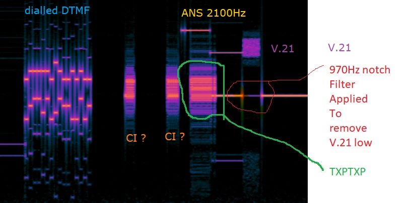
Audacity can display a spectrum, but does not have tools to decode the modem signals in the picture below.
Export the samples from Audacity and paste them into the source code of this webpage, or paste samples into a TextArea. <.P>
Use JavaScript to decode and graph the samples and signals from the filters and UART coded in JavaScript.
Adjust the IIR and UART parameters to find the text sent by the modem. Find the decoded text in the ITU V.18 and V.8 recomendations.
What are the bursts after the DTMF on the left. Are they the CI signal?
Adjust the parameters to these: 300 baud [ 303 ] | V.21(low band) 970Hz:[ 970 ] Hz 1170Hz: [ 1270 ] Hz
Have we decoded the CI signal? 0x0 0x41 ? Find the coding in ITU V.8
Sort out the bugs on this page to get a better decode. Enjoy the moment!!!
It takes a lot of time to document the ideas and concepts used. Some ideas are half remembered from many years ago, and written down to reminder the author. The notes in the source code and web page are for the writer, not the reader.
This page uses IIR filters to look for tones and a 300 baud UART. The red lines are the IIR output, the blue lines are debug.
|
|
300 baud | V.21(low band) 970Hz: Hz
1170Hz: Hz
found
http://jaggedplanet.com/iir/iir-explorer.asp#:~:text=IIR%20Filter%20Explorer%20The%20IIR%20Filter%20Explorer%20is,order%2C%20in%20low-pass%2C%20high-pass%2C%20band-pass%20and%20notch%20configurations.
   input --- filters --- comparator --- UART
 8000 samples per seconds
 300 baud = 26.667
 UARTS normally use a x16 clock
 300 x 16 is 4800Hz clock

 UART - for each time slice increment t
 START,bit0,1,2,3,4,5,6,7,STOP
 use a count down state machine
 0 - stop
 1

 The filter function uses an iir filter.

 The energy is measured using the delayed output squared.

  // take 4 samples
  opA[ i ] =
    z[0]*z[0]
	+z[1]*z[1]
	+z[2]*z[2]
	+z[3]*z[3]

 One of the filters resonated with amplitude about half of the other one so it is doubled.

/*
*
* iir filter.
*
*
--X---[ z-1 ]----[z-1]-----
  |            |           |
  |				k	       -1
  |            |           |
  \------------------------
*
*
from wikipedia:-

Nterms defined here
Kterm selected here
ω = 2 * π * Kterm / Nterms;
cr = cos(ω);
ci = sin(ω);
coeff = 2 * cr;

sprev = 0;
sprev2 = 0;
for each index n in range 0 to Nterms-1
  s = x[n] + coeff * sprev - sprev2;
  sprev2 = sprev;
  sprev = s;
end

power = sprev2*sprev2 + sprev*sprev - coeff*sprev*sprev2 ;

*
*/


/*
* https://sites.google.com/site/hobbydebraj/goertzel-algorithm-dtmf-detection
*/

var z1= "0,0,0,0".split(",")
var z2= "0,0,0,0".split(",")

var k1= "0.5,-0.7,0.2,0.2".split(",")
    k1[0] = 2.0*Math.cos(  2.0*Math.PI*(980*1.0/8000.0) )
    k1[1] = 0.7

var k2= "0.5,-0.7,0.2,0.2".split(",")
    k2[0] = 2.0*Math.cos(  2.0*Math.PI*(1180*1.0/8000.0) )
    k2[1] = 0.7

 function iir2_ts( i, ip,z, k, opA ){

  z[3]=z[2]*1.0
  z[2]=z[1]*1.0
  z[1]=z[0]*1.0
  z[0]= ip*1  +k[0]*z[1]   +k[1]*z[2]

  // take 4 samples
  opA[ i ] =
    z[0]*z[0]
	+z[1]*z[1]
	+z[2]*z[2]
	+z[3]*z[3]

}