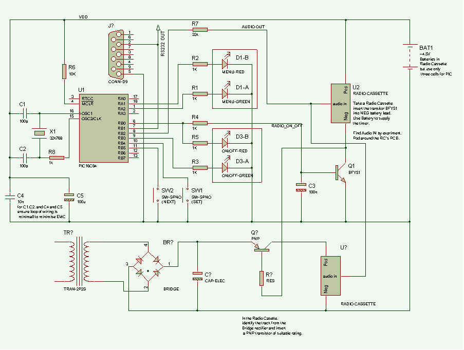
The Circuit Diagram for the Shipping Forecast Timer:-
The circuit is as simple as possible. In the diagram above, there are two arrangements of turning on the Radio, pick one which suits your radio most.
| The shipping forecast timer is a simple timer circuit.
Press the NEXT button to overide the timer. There are 8 ON times and 8 OFF times stored in the EEPROM of the PIC chip. These can be changed and the Time set using the buttons SET and NEXT Buttons. |
 |
The State machine for setting the time and changing the ON/OFF times:
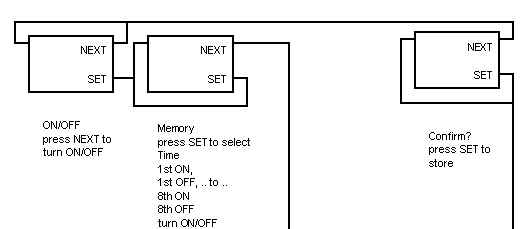  |
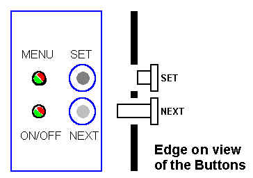
The timer uses the two buttons, the two bi-colour LEDs, and the audio line to control and set the time on the timer. This has taken a lot of work coming up with a design that seems simple and does not require an LCD display.
Ensure the Next Button is easy to press, and the Set Button is recessed, and cannot be pressed without the use of a pen or sharp object.
The NEXT Button is all that is required to turn the tape on and off. The SET button is only required when setting the time.
It is easier to edit the ON/OFF times by connecting, the RS-232 to a VT100 terminal emulator.
On my PC I can just connect the RS-232 output directly to COM1 Rx input, without the need for a TTL to RS-232 driver. Using a terminal emulator set at 1200 baud, setting of the ON/OFF times is much simpler.
The time is output every second.
If you are reveiwing the current on off times they are also output, instead of the current time.
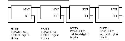
As you enter more digits, the displayed string gets longer, in an obvious way.