The single control meant that each button was multiplex onto this control pin via a resistance as described in the table below:
I had a problem of supermarket lorries delivering at a very early hour, and I wanted to record the lorries arriving. My sleep was being disturbed, but the act of turning the tape on was even more disturbing. I had a minidisc that could record in mono for up to 140 minutes. It does not have a timer to start the recording.
I also had some designs for a timer to turn on a Radio Cassette at sea away from a mains supply to record the shipping forecast. It is broadcast late at night at 00:55, 05:35 and during the day at12:00 and 17:55. One of these timers used an LCD display and a PIC16F84, and is battery powered. Another uses Bi Coloured LEDs and sound to output the time settings.
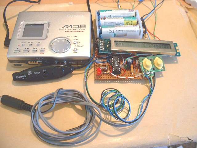
A minor modification of this LCD timer would allow me to turn on the minidisc recording at 04:30 am. All that was required is that the timer emulates the remote control. The original timer uses an LCD from the a surplus source, and they may not be too readily available. The timer has been enhanced so that an RS232 terminal such as a VT100 emulator or Psion Organiser can be used, the LCD need not be used, if unavailable.
| The Awai AM-F5 minidisc recorder's remote control is
small and uses an impossible to get stereo + control 3.5mm
jack socket. The single control meant that each button was multiplex onto this control pin via a resistance as described in the table below: |
|
Button |
Resistance |
Function |
>| |
5k ohms |
PLAY |
rec |
12k4 |
REC |
[] |
19k1 |
STOP |
>> |
27k |
FFWD |
<< |
38k |
FBCKWD |
dsc |
49k1 |
DSC |
enter |
64k |
ENTER |
Vol |
82k to 328k |
VOL |
The volume control is in parallel with the other switches resistors and always connected, and the HOLD switch is inline with the resistances and switches, and is used to prevent accidential operation.
It is now possible to obtain these 3.5mm connectors, from Maplin.
In the end, I modified the remote control unit and soldered a couple of turned pins from an IC socket, onto the ground and control wires.
This is not an easy procedure, but it does allow the timer to be connected by a couple of bits of wire, but leaves the remote control relatively unmodified.
Using the Remote control, these commands are required:
To start recording:
|
To Stop recording:
|
It would be possible to do quite a lot more with the PIC chip, but all I needed was a timer to turn on the Awai minidisc player at 04:30, and then turn it off about 2 hours later.
I modified my timer circuit below:
or using the more popular HD44780 based LCD modules:
To the above circuit I added the circuit below to connect a PIC chip to the remote control pin to control the Awai AM-F5 minidisc player.
The code (75k) is written in MPASM, and consists of:
RT003.ASM - Main Routine
LCD.INC - code to drive the SED1200 based EA-C20017AR module or and HD44780 based 2 x 16 LCD module, define either buildLCDsed1200 or buildLCD_HD44780
AWAI.INC - Code to drive the AWAI minidisc remote control
The PIC code , aiwa.inc, drives the PORT A to simulates open collectors.
; awai.inc
;

; PORTA bits
;
;	Connect the resistances to ground.
;
AWopenCircuitOP EQU	~0
AWstopOP	EQU	~0x04	;	19k1	Stop
AWrecOP		EQU	~0x08	;	12k4	Rec
AWplayOP	EQU	~0x10	;	 5k	Play
				;	27k	FFWD	fastForward
				;	38k	FbckWd	FastBackward
				;	49k1	dsc
				;	64k	Enter


;--------------------------------------------------------------------------
; Sec 4.7	AIWA Control Routine
;--------------------------------------------------------------------------
;
;	To start recording:
;	Over about 4 seconds
;	REC/EDIT
;	REC/EDIT + PLAY
;	O/C
;	PLAY


  IF  0 !=  ( high ( IPjmpTable5End ) - high ( IPjmpTable5Start ) )
    Error "Table straddles Page Boundary "
  ENDIF
IPjmpTable5Start


AWstop  ; Stop minidisc
	MOVLW	low(AWswStop)
	MOVWF	AWstate
	GOTO	AWts
AWstart ; Start recording
	MOVLW	low(AWStartRec)
	MOVWF	AWstate

AWts	; Time slice - this is called once per second,
	; and uses a state machine to work through
	; the sequence of button presses required.
	MOVLW	high($)
	MOVWF	PCLATH
	; simulate open collector operation
	CLRF	PORTA
	BSF	STATUS, RP0	; Select TRIS
	MOVFW	AWstate
	MOVWF	PCL
	; set choice State Table - limited to 2 states and two events
AWswIdle
	; OC all buttons
	MOVLW	AWopenCircuitOP
	MOVWF	TRISA
	MOVLW	low(AWswIdle)
	GOTO	AWend

AWStartRec
	; apply rec/edit
	MOVLW	AWrecOP
	MOVWF	TRISA
	MOVLW	low(AWswRecPlay)
	GOTO 	AWend

AWswRecPlay
	; apply rec/edit + play
	MOVLW	AWrecOP & AWplayOP
	MOVWF	TRISA

	MOVLW	low(AWswRec2)
	GOTO 	AWend

AWswRec2
	; apply rec/edit
	MOVLW	AWrecOP
	MOVWF	TRISA
	MOVLW	low(AWswOc)
	GOTO 	AWend

AWswOc
	; Open circuit
	MOVLW	AWopenCircuitOP
	MOVWF	TRISA
	MOVLW	low(AWswPlay)
	GOTO 	AWend

AWswPlay
	; Apply Play
	MOVLW	AWplayOP
	MOVWF	TRISA
	MOVLW	low(AWswIdle)
	GOTO 	AWend

AWswStop
	; Apply Play
	MOVLW	AWstopOP
	MOVWF	TRISA
	MOVLW	low(AWswIdle)
	GOTO 	AWend


IPjmpTable5End

AWend	MOVWF	AWstate
	BCF	STATUS, RP0
	RETURN
To simulate pressing the remote control buttons, the Port A pin is made a logic low output. To simulate when the button is not pressed, make the Port A pin an Input.
First of all, clear Port A, then set or clear the TRIS A bits to make the pin an input or an output.
The state table below is called once a second until the sequence is completed by jumping into AWts.
To start the sequence, call AWstart to start the AIWA recording, or call AWstop to stop it recording.
This timer worked well and could be modified to emulate other remote controls.
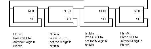
Setting the TIME
The State machine for setting the time and changing the ON/OFF times:
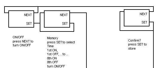  |
Ensure the NEXT button is easy to press, and the SET button is recessed, and cannot be pressed without the use of a pen or sharp object.
The NEXT Button is all that is required to turn the tape on and off. The SET button is only required when setting the time.
At the moment the RS-232 can be connected to a VT100 terminal. Sending '1' and '0' replicates pressing the SET and NEXT buttons. The current time and output status is sent to the terminal apart from during setting. During setting, the current setting is shown, and the digit being set is shown on the right. It's quite an acheivement to get 1200 baud out of the PIC when clocked at 32kHz, as each bit duration is only 6.83 instruction cycles. The RS232 input interrupts the process, including any RS-232 output, corrupting any output going on, but the character input is buffered, and schedules a Button press event, and this is not processed until the pic runs the main loop.
All the code works on the Poll inputs and schedule an event for processing later, principle.
A main loop polls around for any scheduled events. Tmr0 runs clocked by the 32kHz oscillator. It does not interrupt, but the Tmr0 overflow is polled. This happens 4 times a second, and schedules a 1/4 second event, in which the buttons are read and compared to last time, the main timer chain is also run. Minimal code is run in these events, new events are scheduled, for the main loop to find and execute. Button Events reset their respective bits, DoTimeSlice events Set their respective bits, ensure that the service routine sets the button events and resets the DoTimeSlice events. The main loop polls around these events flags and runs any events that need to be run. This method was used from my earliest code as it's more like real time code. It takes the pressure off the limited stack, and is useful to decouple input from output.
Make sure that the control voltages are within what the PIC can cope with. I think that the AM-F5 Minidisc is discontinued, but I think that the design could be adapted without too much effort.
Readers who try the techniques described here entirley at their own risk. No responsibility is assumed for any damage to reader's equipment.