![]() Back to the
Introduction Here is
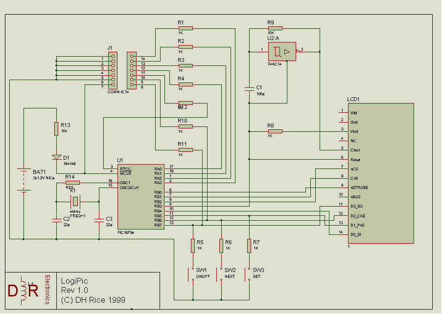
the Circuit Diagram. The LCD needs to be clocked at max 1MHz, and
the PIC is clocked at 4MHz, so U2:a is used to clock the LCD. The
reset line is used to provide the gnd supply to the 74HC14, and
Vlcd. When turned off, the RESET line is driven high to stop the
oscillator, remove the Vlcd and put the PIC into the sleep mode,
with wake up on press of a button.
Back to the
Introduction Here is
the Circuit Diagram. The LCD needs to be clocked at max 1MHz, and
the PIC is clocked at 4MHz, so U2:a is used to clock the LCD. The
reset line is used to provide the gnd supply to the 74HC14, and
Vlcd. When turned off, the RESET line is driven high to stop the
oscillator, remove the Vlcd and put the PIC into the sleep mode,
with wake up on press of a button.