1 Routing around for a generic understanding
2 Contents
1 Routing around for a generic understanding
3.1 From Specifics to Generality
3.4 The Routing Control or Error message
3.5 The Race Condition Control or error
This diagram influences the choice of action.
3.6 Implementation Sets of Structured sets of objects.
4 The users view to the implementation view.
4.1.2 The Routing Control or Error message
5 From condition to Distributed State Machine.
5.1 Distributed State Machines
5.2 Distributed State Machines Compound State machines
6 From condition to Analogue State Machine
3 Introduction
This paper is a collection of understandings about routing in the context of the diagram below:
Traffic is routing from A to D via first choice route A-B-D, and failing that via A-C-D.

I discuss the structure of the data in A and the error and control messages sent into A to affect the routing.
I discuss the aggregation of the routing instances in to sets and these sets into super sets.
I discuss the error and control methods in terms of popular protocols and compare the strengths, weaknesses and omissions.
3.1 From Specifics to Generality
I have been working in the telecomm industry and work on the integration and test of Intelligent networks. I have come to an understanding that many protocols we use mix and match similar concepts from this diagram.
I think that it would be worth trying to list these in the context of the diagram.
I think that new designs should be validated against the generic and proven procedures used in other protocols.
I believe that there are mathematically correct ways of combining the parts.
3.2 Protocols
It has occurred to me that the diagram above can be applied as a reference to discuss various similar routing scenarios in different protocols.
I would like to prepare a table comparing the features of each protocol.
Here is a small list of protocols that can be mapped onto the diagram above.
- Circuit based switching of calls from A to D via B or C
- Callers dial a sales line number D and talk to either agent B or C who knows about the common product D
- TCP/IP sets up a connection from A to D, using the IP network
- TCAP/SCCP set up transactions via B and C to D
- Circuit based signalling sets up calls using circuits from A to B to D or A to C to D and use Automatic Alternative Routing to pick the route.
- An Intelligent Network SCP sets up a speech calls to one of a list of SRF. The SRF act as transit nodes and the call context is forwarded onto D to request the prompts to be played.
- MTP STPs traffic from A to D using MTP routes over Linksets.
3.3 From Single to Multiple
The diagram does not show anything about the number of concurrent calls or transactions that can be supported.
It is normally discussed in terms of one call of many.
The diagram implies a set of resources, and it is worth discussing how the different protocols refer to the instances of resources.
For example circuit based switching may has say 120 circuits using 4 PCM systems. between A-B, B-D, A-C, and C-D. The signalling refers to the timeslots on each PCM system using circuit identification codes. These use a mapping. to convert between PCM system and Timeslot to CIC. This mapping has be be mutually agreed by the databuilders who configure A and the databuilders who configure B, so it is important to keep this constant.
Other protocols keep the transactions separate by the client supplying a unique reference which server includes the information sent back.
Other Protocols keep the connections separate by dynamically allocation a source port number and sending to a common port number. The client and server use these port numbers to identify the processing instance.
Sometimes discussion extends to discussing congestion and what happens to a call at the limit of available resources.
Discussion of management of resources also takes place.
The diagram is implemented by structured sets of objects.
3.4 The Routing Control or Error message
The destination node can send a control message to update state machine in the source that summarises the availability at the destination.
Alternatively, a call can be rejected with an error message, to indicate that a call attempt is not allowed in the current status.
As an error message can only be returned when a call attempt is made, the source will need to routinely poll to see if the status has changed.
3.5 The Race Condition Control or error
The control message is sent when the destination becomes unavailable. However there is a delay for the message to be sent received and processed. At high traffic there is a good chance that traffic will still arrive after the control has been sent.
This traffic could be rejected using an error message, and after the control message is received, traffic is no longer offered to the destination, but is backed off in the source node.
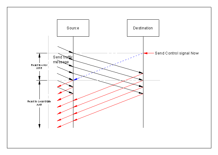
This diagram influences the choice of action.
This diagram influences the choice of action.
If you set out to design using the control method, what should you do when you get an error message?
My diagram shows that the error signals arrive after the control signal, so there is no need to do anything special until the control message is received.
What choices have you got?
3.6 Implementation Sets of Structured sets of objects.
Going from the single to the multiple offers a wide number of options.
I like the associative array of objects.
The index array can be constructed from a vector of references to the members of the sets.
For example: NodeA has two routes, each with 120 circuits.
Have an global associative array for the whole diagram.
Routes:-
AB
AC
BD
CD
We could structure the data for node A as NodeA.ToD.ViaB and NodeA.ToD.ViaC
Here is some pseudo JavaScript to illustrate this.
function newData( available, nextNode ){
// return an initilized object
var r = new Object()
r.available = available
r.nextNode = nextNode
return r
}
dataA = new Array() // an associative array, indexed by a string.
// set up
dataA[ NodeA.ToD.ViaB ] = newData( true, NodeB )
dataA[ NodeA.ToD.ViaC ] = newData( true, NodeC )
4 The users view to the implementation view.
I think that it is worth discussing the clash of cultures of telecom working from telephony circuits to Computer people whos model is based on the remote procedure call in a pre-emptive operating system.
A user of UNIX or DOS may write a small program or shell script and think of their program running in its own little world.
They define functions calls to break down the problem and use system functions. These system functions may include remote procedure calls. Remote procedure calls look like an every day function with parameters and return a value, but they send a message to a remote computer to run the function, and it returns the values passed back to the caller.
The concept of the remote procedure call allows a user to request information from a remote server without
the need to manage the signalling and establishment of routing. Often, when these functions are called, the program blocks until the information is received form the remote computer. Another process configures this.
Of course Unix is a multi user multi process operating system, so it must manage the multiple instances and the client server model evolved. The user may be given a handle e.g. a file handle by a system function call to access the remote object, which the user must use, but whose value is of no importance to the user. However, should the user forget it or corrupt it, the consequences may be dire, when using the associated functions that need the file handle.
As far I a remember, in the late 1970s before computers and digital signalling, it was all about indicating calls on a copper speech pair by use of conditions. The phone would loop the line and the exchange would use relays to let the dial pulses to rotate a switch or uni-selector to select a circuit. These were clever circuits that did the functionality.
We got C7 signalling, and then the signalling moved from hardware and clever circuits to software. Now instead of conditions on circuits, the exchange would send a message, and the exchange would look for the conditions and convert them to a message name. You could produce a neat and tidy list of inter exchange messages that were formatted in a similar and consistant way. You would write software in terms of function calls and software would look the same, except that the formatting was up to the programmer, and coding standards are used to force a consistent format. Good programmers would take this functional decomposition neatly into the
Before you had a document that would describe the conditions and circuit diagrams. The hardware would be designed to use consistent card frames and be painted using the same colour paint, but the interface would be different for each card.
4.1.1 The Routing.
The routing works by working through the list to find an available destinations. The destination is the user node, but there are a choice of transit nodes to route through.
The transaction / call is offered to the transit node.
If it can route to the user node it does, otherwise, it is rejected with an error message. Sometimes, the call/transaction is offered to the to the other transit node to get to the user node.
The transit node can send a control message to the source node, to indicate that the destination is unavailable. The source node is expected to update a state machine that indicates the status at the transit node.
It does not have to wait to be asked by the source.
So if the transit node detects a fault on the transmission system from the source to the transit, the transit node blocks all the circuits carried over the transmission system. The source node marks these circuits as unavailable due to a hardware fault, so when the routing function scans for an available circuit, they are not selected.
After a restart of the source node, it may have forgotten which control messages it has received. This can lead to deadlock if it thinks it has received a message to indicate unavailability but the transit node thinks it has sent an availability message. No traffic is sent via this transit node over the resources controlled by these control messages.
Alternatively, after the restart, the source node may think that it can send messages to the transit node, but it was previously told that it was unavailable. Unwanted traffic arrives, and may cause routing failures.
I have been vague about what the control messages indicate. In a telephony call you have a sequence of messages, an initial message, and messages to indicate significant events like ringing or answer and call release.
Where there are many circuits sharing the same route, you may get overlapping calls, and very rarely a period of when a call is not in place on a circuit. So how do you stop traffic. You wish to prevent new calls from starting, but leave existing calls to time out.
With the introduction of common channel signalling, the signalling also changed from a condition based signalling to an event based message based signalling.
Instead of a condition persisting on a set of control wires, a message was sent when there was a change in condition.
This has lead to a problem in that if the signalling connection fails, it may go unnoticed.
A fixed line phone is off hook and current flows to power it. When the handset is replaced, the current is broken, indicating that the phone has gone on hook again.
In ISDN, this signalling is done with messages. If the phone is unplugged, the loss of signalling channel prevents the call being cleared as the clear/releaseCall message cannot be sent.
The loss of the physical should result in the call being cleared due to a fault.
4.1.2 The Routing Control or Error message
The destination node can send a control message to update state machine in the source that summarises the availability at the destination.
Alternatively, a call can be rejected with an error message, to indicate that a call attempt is not allowed in the current status.
As an error message can only be returned when a call attempt is made, the source will need to routinely poll to see if the status has changed.
5 From condition to Distributed State Machine
The diagrams below show combinatory logic.

The diagram below feeds back some outputs to form a state state machine. This example is an unclocked one.

The diagram feeds back some outputs to form a state machine. This means that history is used to affect the outputs.
The history is often stored in a state variable. A state machine may have many states.
In a clocked state machine the states are latched. You could have a state machine where the state is stored in more than one latch and each latch is clocked by different clocks.
5.1 Distributed State Machines
It is possible to have a clocked state machine where the state latches are clocked by different clocks.
This state machine has a compound state. The combined state could be expressed as:
State = stateClockedByClockA + stateClockedByClockB
Consider what clocks the latch. It is possible that a remote system latches one latch and another clock latches another.
Clocks could be:
A repeated timer tick that happens periodically.
An output of the combinatory logic could clock the latch.
The clock could be a remote input.
There may be a requirement that the state is backed up in a remote store.
The clock copies the state into a remote store and the remote store is polled to update the
It may be that a remote system copies the state into a remote database, and the database can update the state.
It is not essential that the state machine is located on logic that is located in one place.
The latches could be in local memory, shared memory, even a remote database with a local copy.

5.2 Distributed State Machines Compound State machines
State machines are often replicated, e.g circuit handlers, connection handlers. They could share half of the compound state, e.g the states held in shared memory.
Maybe the Combinatorary logic is run by a computer processor, and in a multi processor system, which ever Processor is available.
If the state information is stored in a remote database a local copy may be cached to speed up processing. It is important that the local copies are faithful copies and a mechanism is put in place to update the copies.
The updates could either be by the database pushing out updates to known copies, or updates being requested as and when. This is similar to the Control or Error mentioned above.
An example of this is how browsers cache web pages and javascript files on the computer where the browser is running. When a page is opened, the files searched for in local cache, and if found, they do an HTTP request to see if the web page has been updated. The local copy date stamps the local copy and compares this to the Servers version. A newer version is downloaded , otherwise the local copy is used.
State machines may be:
|
Replicated |
The same combinatory logic is used for many different instances of the state data. |
|
Replications Partitioned |
the replications of the state state are stored on more than one computer |
|
Distributed |
The same state data ( or local copies of ) affects many instances of the combinatory logic. |
6 From condition to Analogue State Machine
The diagrams below show combinatory logic.
The diagram below feeds back some outputs to form a state state machine. This exaplme is an unclocked one.
The diagram below feeds back some outputs to form a state state machine. This example is an unclocked one.
The diagram below feeds back some outputs to form a state state machine. You can model analogue circuits using Ohms Law, V= R I and these functions I = 1/R V, dV/dt = 1/C I, dI/dt = 1/L V

Ohms law converts Voltage to current and current to voltage. Kirchoffs law states how the current through a component is based on the current through adjacent components, and how voltages across a component is the sum of voltages around a loop of adjacent components.
Use Kirchoffs law to wire the circuit together, so using the ohms law.
For each component, you have to decide if the voltage of current through it is calculated. The Inductors and capacitors are differentials and you have to integrate these before feeding back the voltage of current.
This means that you write a vector expressing the Voltage across or the Current through a component, and then use a matrix to express the Kirchoff equaltions and a matrix to express the Ohms law.
We get
[V] = [K] [ R] [ V]
[I] = [K ] [ 1/C ] [I]
[V] = integral ( [K][1/C][V ] )
[I] = integral ( [K][1/L][I ] )
The important rule is that when choosing if a component is chosen to be calculated as a Voltage from the current through it or as the current through it based upon the voltage across it.
You have to choose if the component is a dependant Voltage or dependant Current, and ensure that your dependant voltage components are based on currents in adjacent components multiplied by the components resistance.
If you choose to use dependant currents, Sum the voltage across components that are in the loop connected from one end to the other and divide by the resistance.
If you have two resistors, R1 and R2, then you can express
Vr1 = Ir1 x R1
Vr2 = Ir2 x R2
Although you calculate Vr1 and Vr2, you have not calculated Ir1 and Ir2.
Express the formulae as:
Vr1 = Ir1 x R1
Ir2 = Vr2 / R2
Now is you can express Ir1 as a function of Ir2 and Vr2 as a function of Vr1.
When working out a set of Kirchoff equations, you need to draw a tree of components dependant on the voltage.
We have a simultaneous equation which can be solved.
Using Gausian elimination, it is possible to reduce the equations down to the derivative, which can be integrated numerically to work out the voltages across the capacitors
The diagram is an Analogue state machine,

7 Naming Conventions
This comment is useful and I believe would help speed up the project delivery.
I once worked on a project that had 100,000 symbols. They say that most educated people have a vocabulary of 10,000 words. Being expected to understand the purpose of 100,000 symbols is obviously beyond the educated person. Some structure to the names is required so that you can work out that you can ignore the symbol as irrelevant to what you are working on.
Adding a type coding to the symbol name also tells you how to treat it.
e.g.
Suppose I have a structure to the leakyBucketData.
I could have an array of leakyBucketData and in the control group I could have a pointer to an instance of leakyBucketData.
If you add postfixs to define the type you end up with symbols:
leakyBucketDataT - type
definition
leakyBucketData - Instance of leakyBucketDataT
leakyBucketDataA - Array
of instances of leakyBucketDataT
leakyBucketDataP - Pointer to instance of leakyBucketDataT
or
struct leakyBucketDataS {
int level;
int leak;
}; -
structure definition
typedef leakyBucketDataS
leakyBucketDataT; - type definition
leakyBucketDataT lb; - instance of leakyBucketData
leakyBucketDataT lbA[100]; - Array of instances of leakyBucketData
leakyBucketDataT *lbP; - Pointer to instance of
leakyBucketData
This is much better than:
struct leakyBucketData { };
struct leakyBucketData lb; -
instance of leakyBucketData
struct leakyBucketData lb1[100]; -
Array of instances of leakyBucketData
struct leakyBucketData *lb2; -
Pointer to instance of leakyBucketData
This is much easier to read and maintain.
leakyBucketDataT - type
leakyBucketDataT lb; - instance
leakyBucketDataT lbA[100]; - array
leakyBucketDataT *lbP; - pointer
You could argue that this seems to be tautological as the postfix duplicates the context. lbA is a an array as it has [100] after the definition, lbP is a pointer as it has a * in front of it. However, this means you need to constantly refer to the variable declarations to know the type if you do not postfix the symbol names and use them out of context. This wastes time and adds complexity.
What is easier to read and understand
lb = ...
lb1 = ...
lb2 = ...
or
lb = ...
lbA = ...
lbP = ...
In a C program you often malloc memory and free it off. You call malloc and end up with a pointer to the memory block.
One problem that I could never get my head around is who is responsible for freeing it off.
Obviously a function has local storage which persists for the duration of the function call and the local memory is on the stack.
If a function needs to send a message, you need to allocate memory, populate it, and pass it on to a message queue.
8 Naming Conventions
This comment is useful and I believe would help speed up the project delivery.
I once worked on a project that had 100,000 symbols. They say that most educated people have a vocabulary of 10,000 words. Being expected to understand the purpose of 100,000 symbols is obviously beyond the educated person. Some structure to the names is required so that you can work out that you can ignore the symbol as irrelevant to what you are working on.
Adding a type coding to the symbol name also tells you how to treat it.
e.g.
Suppose I have a structure to the leakyBucketData.
I could have an array of leakyBucketData and I could have a pointer to an instance of leakyBucketData. Often you see code like:
struct leakyBucketData { }
leakyBucketData lb; - instance of leakyBucketData
leakyBucketData lb1[100]; - Array of instances of leakyBucketData
leakyBucketData *lb2; - Pointer to instance of leakyBucketData
You end up with symbols which are difficult to tell apart.
If you add postfixs to define the type you end up with symbols:
leakyBucketDataT
- type definition
leakyBucketData -
Instance of leakyBucketDataT
leakyBucketDataA - Array of instances of
leakyBucketDataT
leakyBucketDataP - Pointer to instance of leakyBucketDataT
or
struct leakyBucketDataS {
int X;
float Y;
}; - structure definition
typedef leakyBucketDataS leakyBucketDataT; - type definition
leakyBucketDataT lb; -
instance of leakyBucketData
leakyBucketDataT lbA[100]; - Array of instances of leakyBucketData
leakyBucketDataT *lbP; - Pointer to instance of leakyBucketData
This is much better than:
struct leakyBucketData { }
leakyBucketData
lb; - instance of
leakyBucketData
leakyBucketData lb1[100]; - Array of instances of leakyBucketData
leakyBucketData *lb2; - Pointer to instance of leakyBucketData
This is much easier to read and maintain.
leakyBucketDataT - type
leakyBucketDataT lb; - instance
leakyBucketDataT lbA[100]; - array
leakyBucketDataT *lbP; - pointer
You could argue that this seems to be tautological as the postfix duplicates the context. lbA is a an array as it has [100] after the definition, lbP is a pointer as it has a * in front of it. However, this means you need to constantly refer to the variable declarations to know the type if you do not postfix the symbol names and use them out of context. This wastes time and adds complexity.
What is easier to read and understand
lb = ...
lb1 = ...
lb2 = ...
or
lb = ...
lbA = ...
lbP = ...